
Difficulty
Moderate
Steps
15
Time Required
00:05:00 - 00:10:00

User-Contributed Guide
This guide is not managed by the site's staff.
Quiz
0
Introduction
This guide is a walk through of the complete replacement of an AVA M.2 NVMe Carrier card and M.2 NVMe SSD in a Leopard V2 server. This guide targets maintenance of a sever in a Discovery Fast Start.
If your servers are rack mounted or in another configuration, please locate the appropriate guides for server removal and installation.
-
-
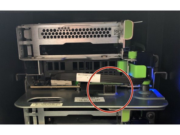
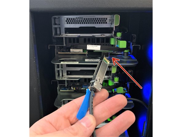
Disconnect the 10G SFP+ cable from the NIC (Network Interface Controller) card by first pulling the blue pull-tab and then the cable directly out from the server.
-
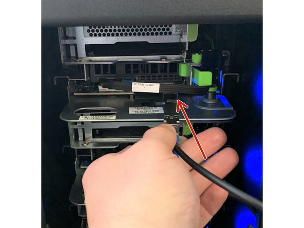
Move cable to the side for server removal.
-
-
-
Locate the server to be serviced in the Discovery Fast Start.
-
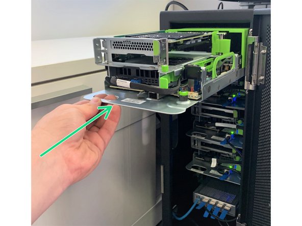
Pull the green retention plunger upwards and twist 90 degrees to lock in the upright position.
-
Using the handle, carefully pull the server away from the Discovery Fast Start.
-
-
-
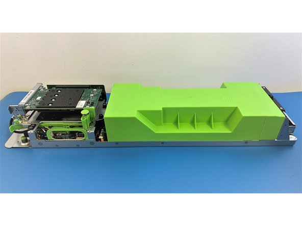
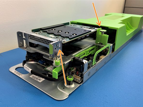
Place the removed Server on an ESD safe cart or workbench.
-
Orient the server with the handle to your left, as shown here.
-
-
-
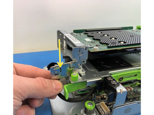
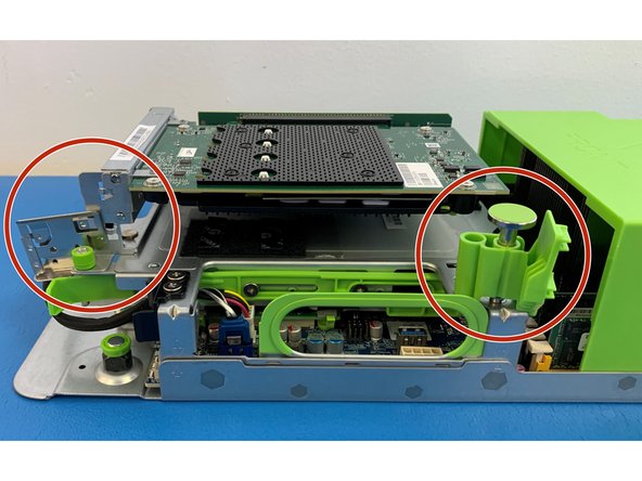
To remove the AVA M.2 carrier card by unhooking the metal hook tab on the left side of the bracket.
-
-
-
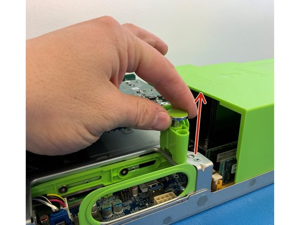
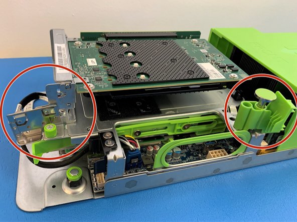
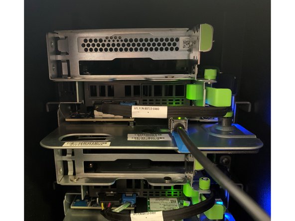
Locate the green retention plunger at the right side of the AVA assembly, next to the large green chassis cover.
-
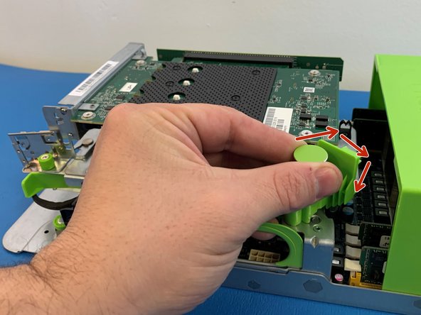
Pull the green retention plunger upwards and then turn 90 degrees clockwise to release the AVA M.2 carrier card.
-
-
-
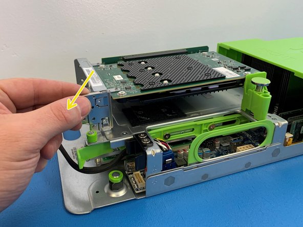
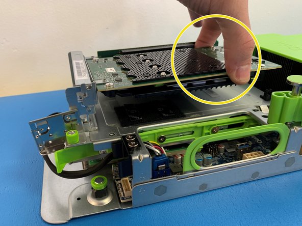
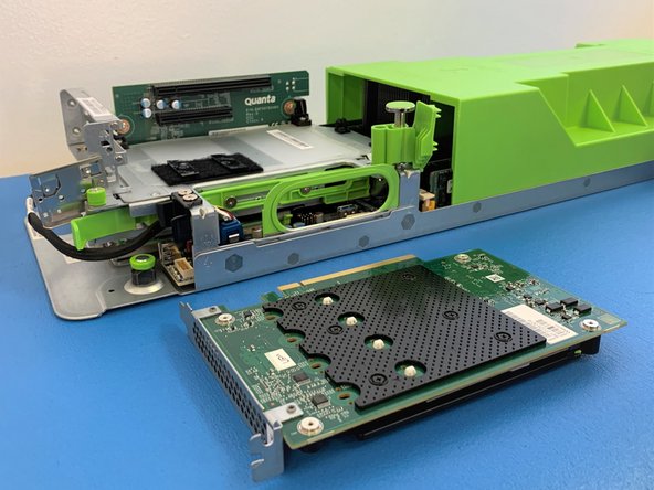
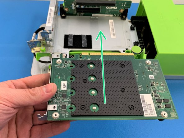
Grasp the AVA M.2 carrier card by the edges and gently pull it out of PCIe Riser card socket.
-
Place the AVA M.2 carrier card on ESD safe surface
-
-
-
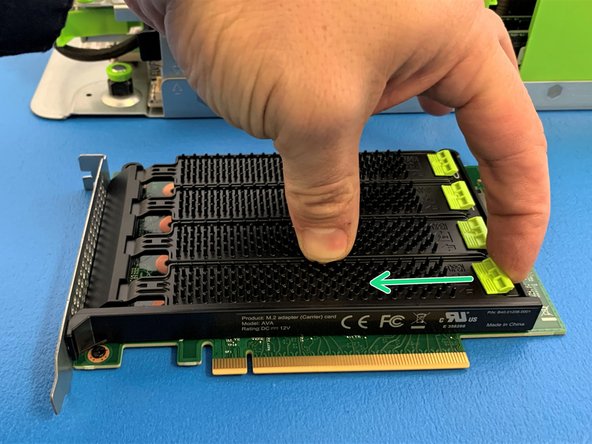
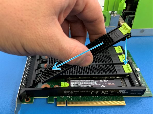
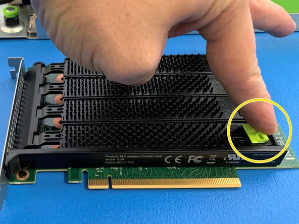
Remove the NVMe metal cover by first pulling green tab towards the center of the AVA card and lifting up.
-
Make sure the thermal pads on the metal cover stay in place.
-
-
-
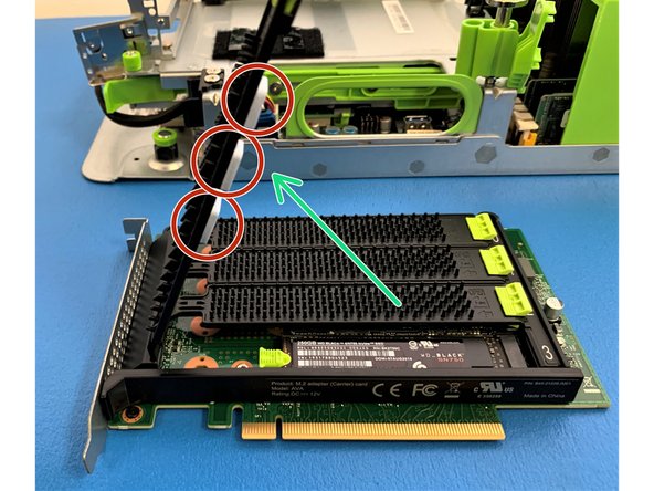
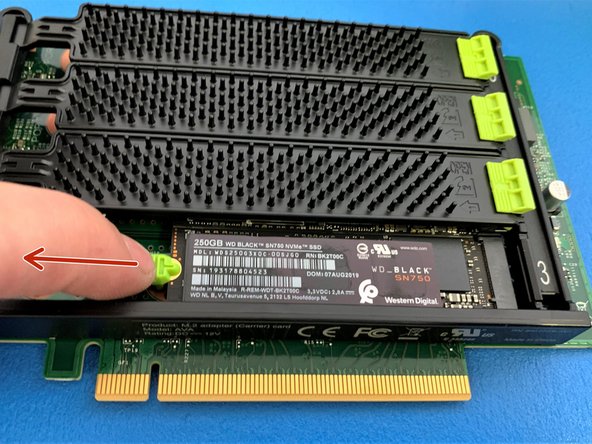
To remove NVMe SSD pull the green tab away from the SSD as shown.
-
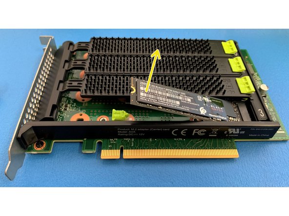
The SSD will automatically lift up.
-
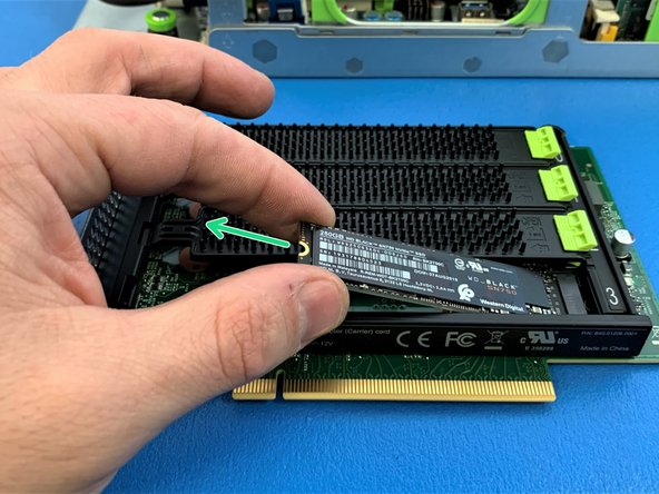
Gently pull out the SSD out of the socket.
-
-
-
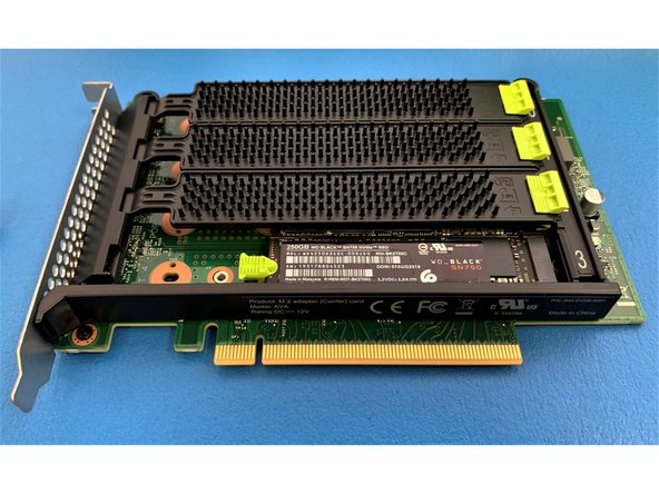
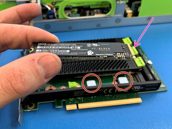
Ensure the 2 thermal pads are present on the AVA M.2 NVMe carrier card before installing the SSD.
-
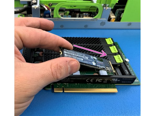
Identify the correct orientation of the new M.2 NVMe SSD based on the socket.
-
-
-
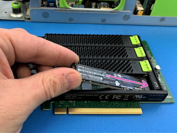
Gently insert the M.2 NVMe SSD into into the AVA M.2 NVMe carrier card.
-
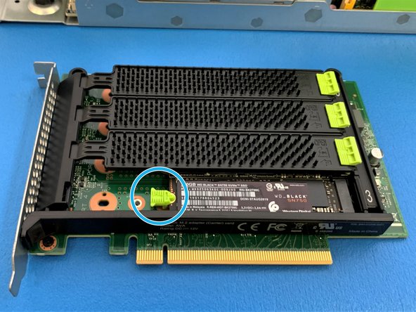
Pull back green tab, gently push the SSD down and release the green tab to lock the SSD in place.
-
-
-
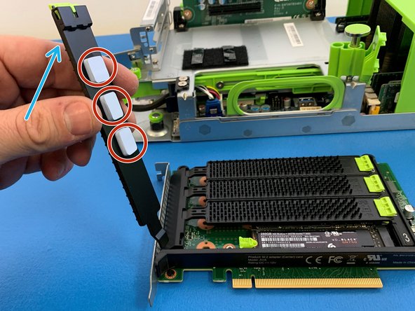
Install previously removed metal cover.
-
Make sure the thermal pads are present and secure on the metal.
-
Close the cover by pulling the green tab towards the front of the card and then releasing to lock once the cover is seated.
-
-
-
Carefully re-install the AVA M.2 NVMe carrier card into the server by slowly sliding it into the PCIe Riser card socket.
-
Close previously opened metal lock and the green retention plunger back to their original positions.
-
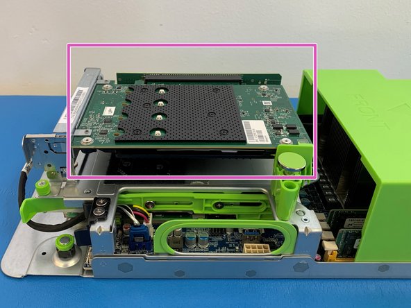
When properly installed the AVA M.2 NVMe carrier card should be secured as shown.
-
-
-
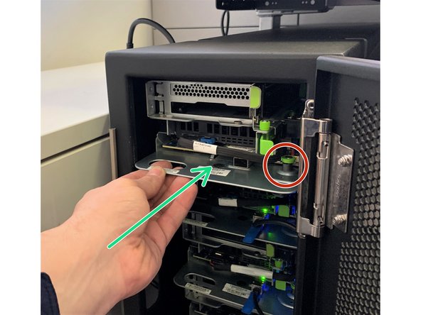
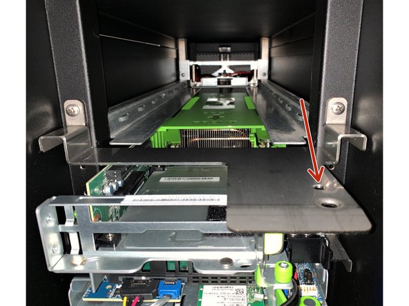
Carefully slide the server back into the Discovery Fast Start.
-
Make sure that server is commpletely inserted and green retention plunger is inserted into the second hole on the metal bracket
-
-
-
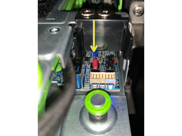
Carefully insert the 10G SFP+ cable into the NIC (Network Interface Controller) port, ensuring it locks into place.
-


Cancel: I did not complete this guide.
One other person completed this guide.