Difficulty
Moderate
Steps
12
Time Required
00:10:00 - 00:20:00
- Big Sur Motherboard Replacement 12 steps

User-Contributed Guide
This guide is not managed by the site's staff.
Quiz
0
Tools
Parts
No parts specified.
-
-
Disconnect network cables from the front of the Big Sur
-
Then release the two locking levers on either side of the Big Sur
-
-
-
Pull the Big Sur out until the rear of the chassis clears the support rail above
-
Unscrew the 2 locking screws on the front of the server
-
Pull the cover straight forward to disengage the anchor pins. The cover will move only about 1/2". Then Lift and remove the cover. Place in a safe location out of the way from people.
-
-
-
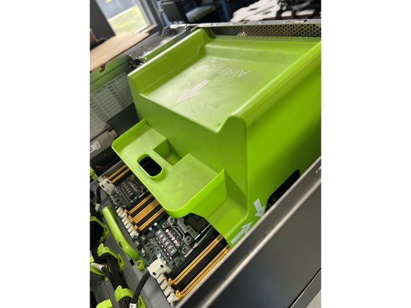
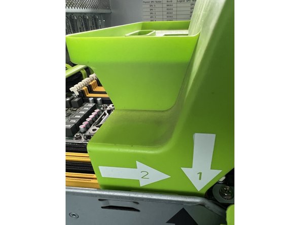
Remove the green air flow baffle by pulling it towards the rear of the unit and then lifting up.
-
Note the instruction arrows are in the order of install. Reverse for removal.
-
-
-
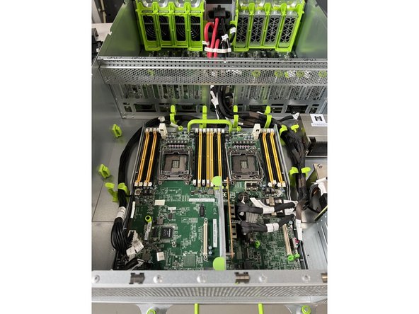
There are thirteen cables to be disconnected. Each will be shown in detail
-
-
-
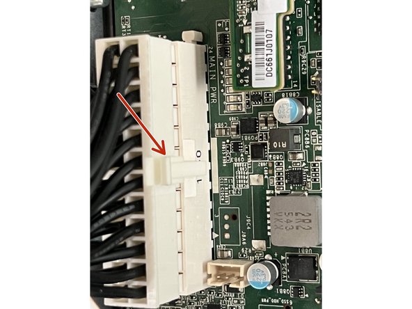
Remove the four riser card connections.
-
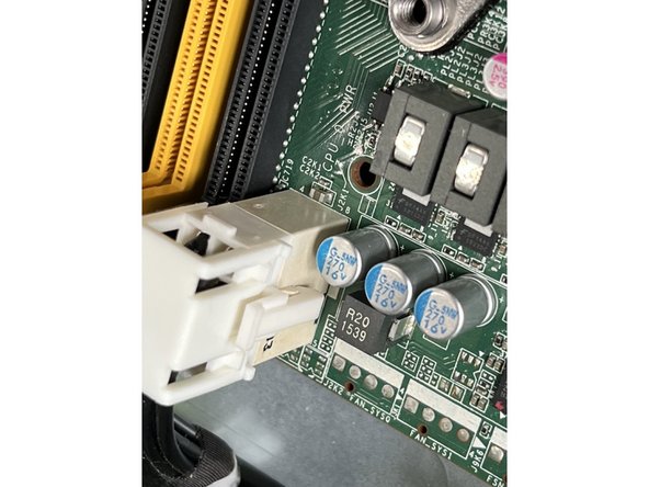
Each connector has a push tab. Depress the push tab to release
-
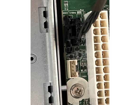
Also unplug the small cable attached to the large cables shown. It press fits to a white socket and can be removed by gently pulling on the connector.
-
-
-
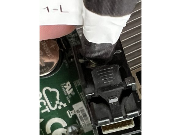
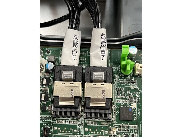
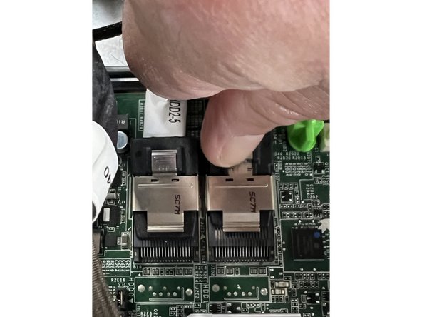
Remove the two disk connectors on the right side of the board.
-
Depress the metal tab gently and slide the connector horizontally.
-
-
-
Disconnect both cables by grasping the plastic connector and pulling gently straight up.
-
-
-
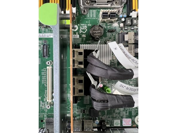
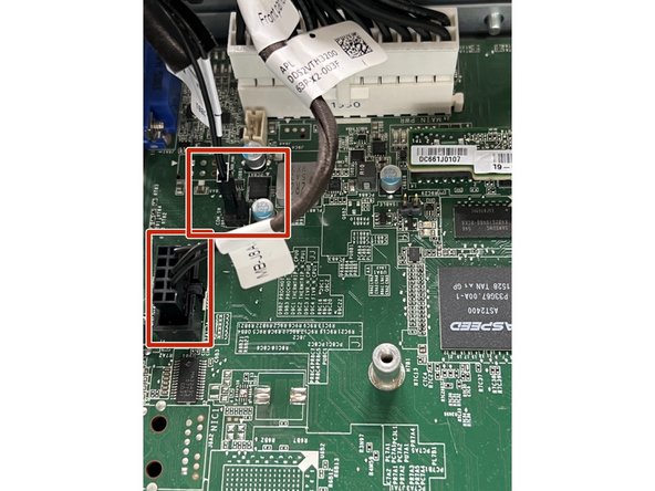
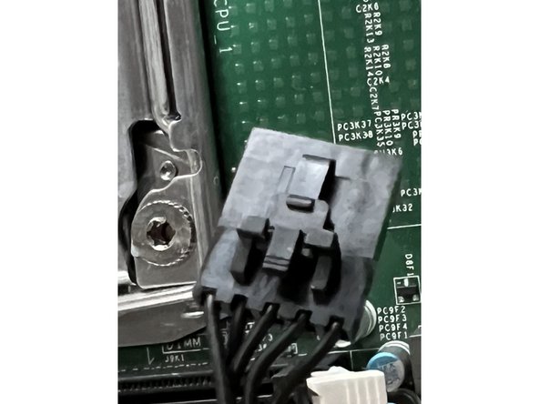
Pull the main GPU connector by depressing the top of the locking clasp and pulling the sides of the connector.
-
Remove the smaller black connector. It too has a small locking clasp. Depress the clasp and pull the connector housing straight up.
-
-
-
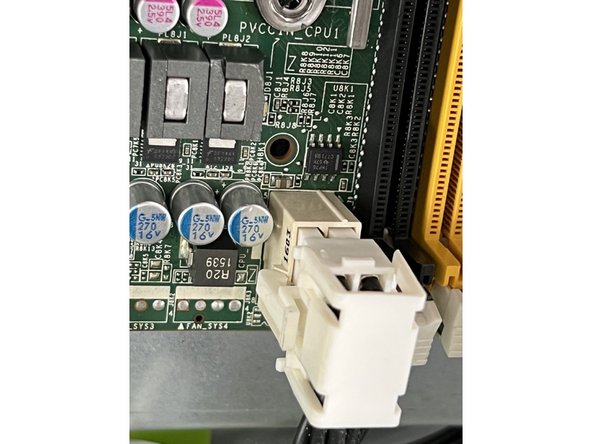
Remove the two final connectors at the rear of the board by depressing the locking claps and pulling upwards
-
-
-
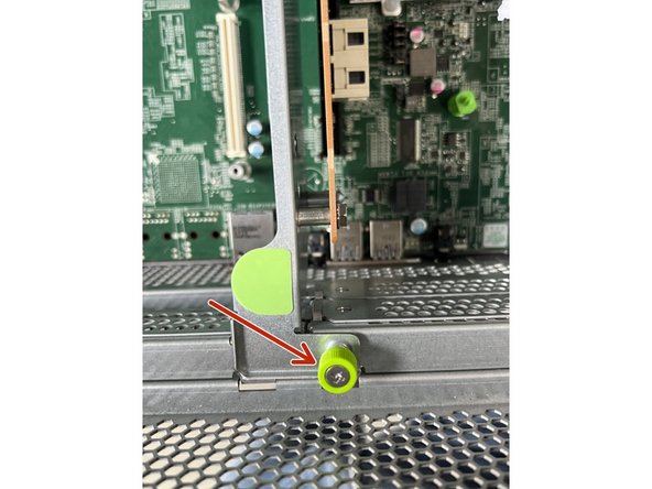
Loosen the screw anchor connecting the PCI board to the front of the chassis. The screw is designed to be loosened by hand but a Phillips screwdriver may be required.
-
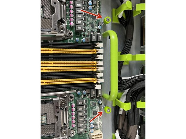
Loosen the two anchor screws at the rear of the board.
-
The screws should not be removed entirely. Loosen only until they are not connected to the chassis.
-
-
-
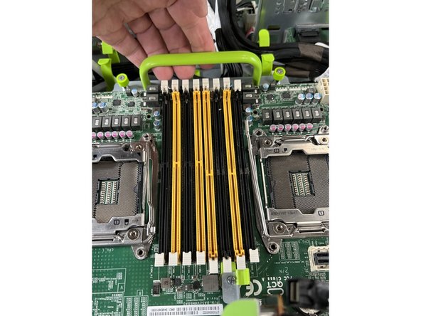
Ensure all of the disconnected cables are out of the way.
-
Gently pull back and up on the handle to disengage the front panel connectors and free the board.
-
-
-
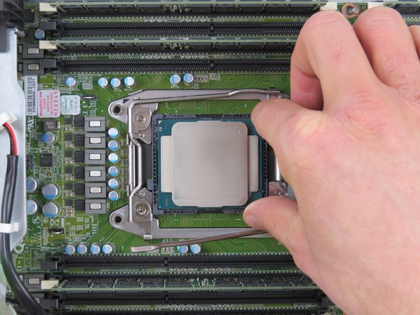
If you need to move the memory and CPUs from the original motherboard to the replacement. Do that now.
-
The Leopard for Open Rack V2 guides describe CPU and memory replacement. The Big Sur layout is different but the procedure is the same.
-