Introduction

Overview

This guide demonstrates how to replace a bus bar clip in an Open Vault system. == Acronyms and Terms ==

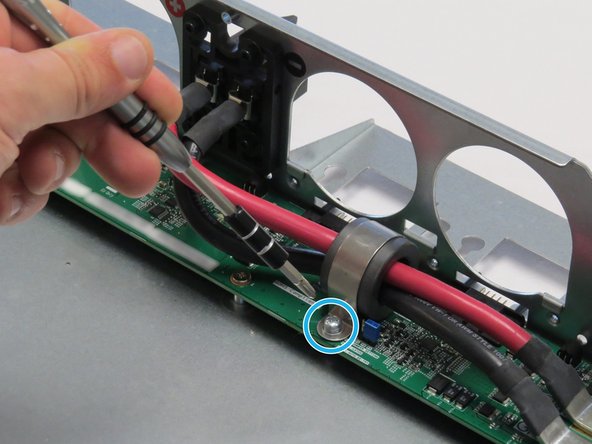
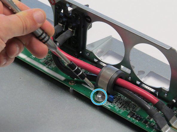
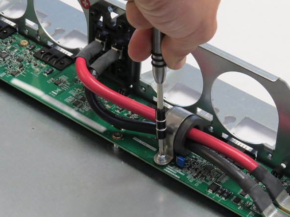
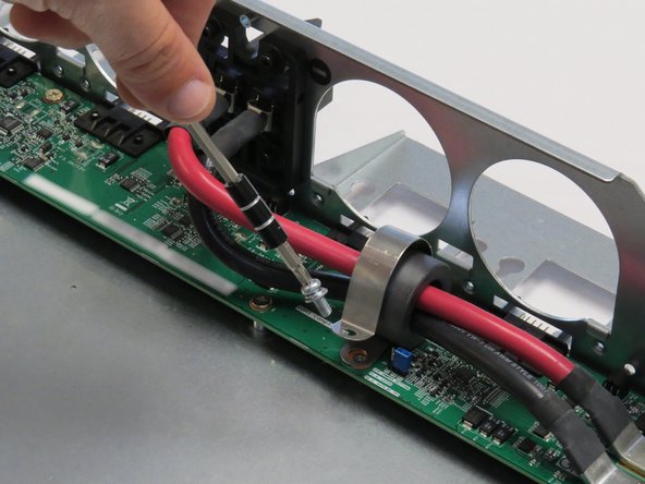
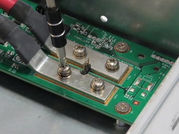
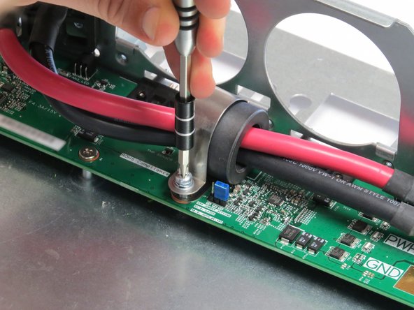
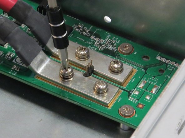
  1. Unscrew one Phillips #2 screw securing the bus lead management clip to the fan controller board. Unscrew one Phillips #2 screw securing the bus lead management clip to the fan controller board. Unscrew one Phillips #2 screw securing the bus lead management clip to the fan controller board.
    • Unscrew one Phillips #2 screw securing the bus lead management clip to the fan controller board.

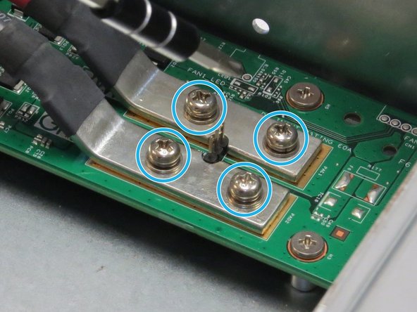
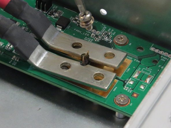
  2. Unscrew four Phillips #2 screws that secure the bus bar leads to the fan controller board. Unscrew four Phillips #2 screws that secure the bus bar leads to the fan controller board. Unscrew four Phillips #2 screws that secure the bus bar leads to the fan controller board.
    • Unscrew four Phillips #2 screws that secure the bus bar leads to the fan controller board.

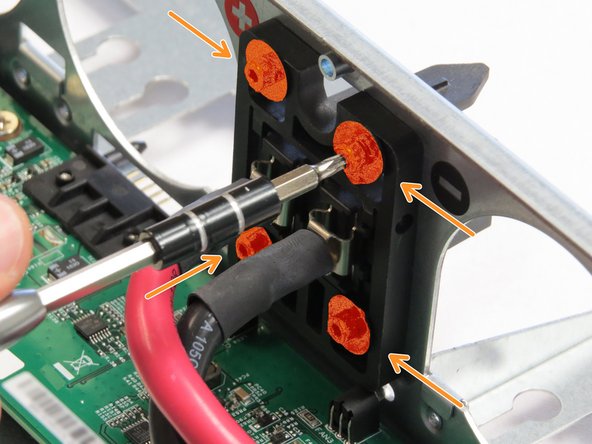
  3. Unscrew four Torx T10 screws.
    • Unscrew four Torx T10 screws.

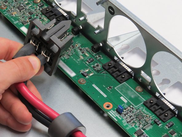
  4. Remove the bus bar clip from the Open Vault chassis. Remove the bus bar clip from the Open Vault chassis.
    • Remove the bus bar clip from the Open Vault chassis.

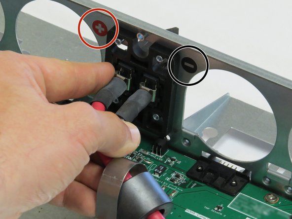
  5. Insert a new bar clip into the chassis.
    • Insert a new bar clip into the chassis.

    • It is important to ensure that positive and negative lead polarity is oriented as indicated by the markings on the chassis, as annotated. Power polarity is indicated as follows:

    • PWR: (+)

    • GND: (-)

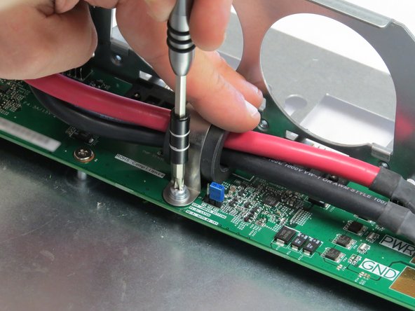
  6. Screw in the Phillips #2 screw to secure the bus lead management clip to the fan controller board. Screw in the Phillips #2 screw to secure the bus lead management clip to the fan controller board.
    • Screw in the Phillips #2 screw to secure the bus lead management clip to the fan controller board.

  7. Screw in four Phillips #2 screws to secure the bus leads to the fan controller board.
    • Screw in four Phillips #2 screws to secure the bus leads to the fan controller board.

    • It is important to ensure that positive and negative lead polarity is oriented as indicated by the markings on the chassis. Power polarity is indicated as follows:

    • PWR: (+)

    • GND: (-)

Conclusion

Dozuki System

Member since: 9/24/09

1 Reputation

142 Guides authored

0 Comments

Add Comment


View Statistics:

Past 24 Hours: 0

Past 7 Days: 0

Past 30 Days: 0

All Time: 0