
Introduction
Overview
This guide demonstrates how to replace a bus bar clip in an Open Vault system. == Acronyms and Terms == * HDD - Hard Disk Drive * Mini-SAS - Mini Serial Attached SCSI * SCSI - Small Computer System Interface === Additional Notes === It is not absolutely necessary to remove trays from the Open Vault chassis to replace the Powerblade cable. This section of the replacement guide may be treated as a preference.
-
-
The server can be powered off remotely or on the hardware itself.
-
Remote Power Down: Login to the server to power it off.
-
shutdown -h now;exit -
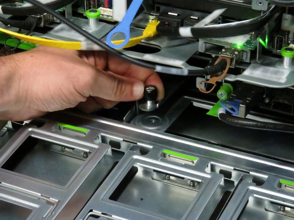
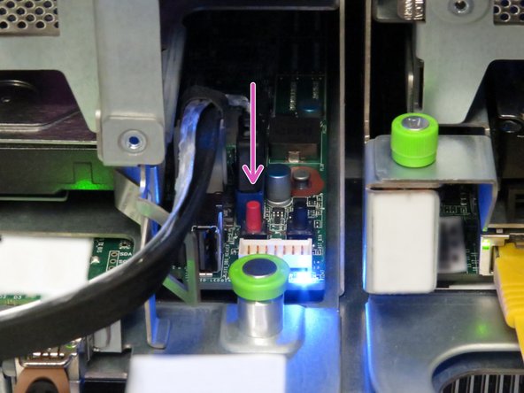
Hardware Power Down: Press and hold the power switch for at least three seconds, as annotated.
-
-
-
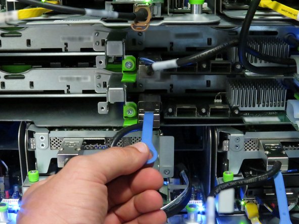
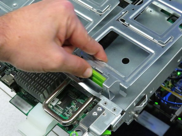
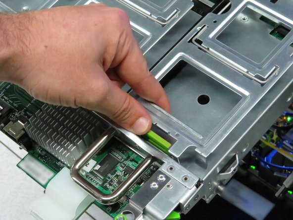
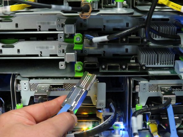
Disconnect the Mini-SAS cable from the storage tray.
-
Use the pull-tab to disconnect the cable, as shown.
-
-
-
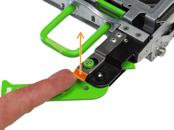
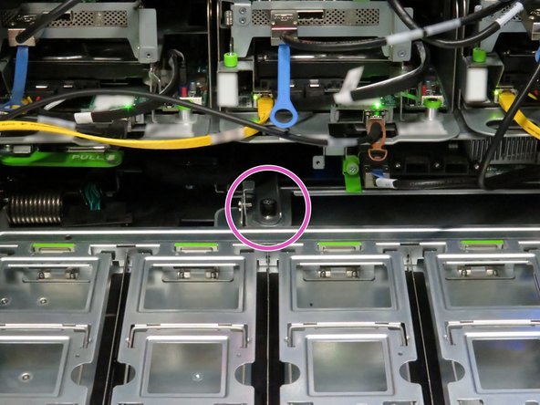
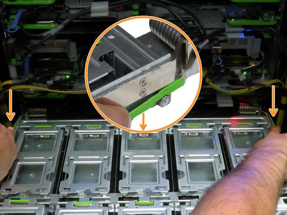
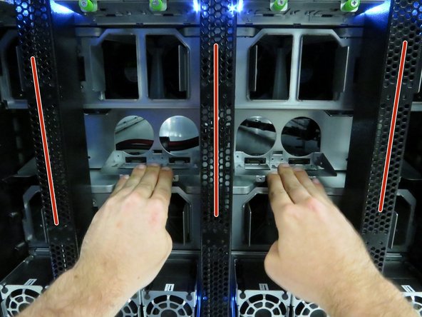
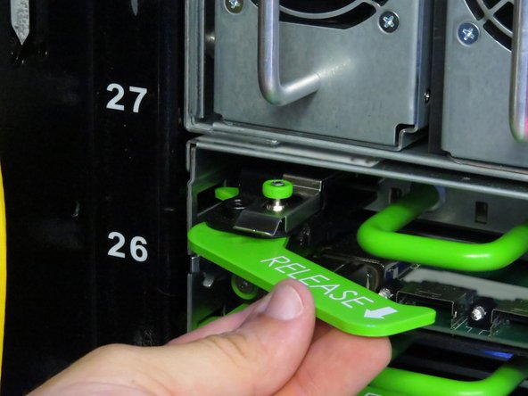
Locate the two tray release levers.
-
These release levers secure the tray to the storage chassis.
-
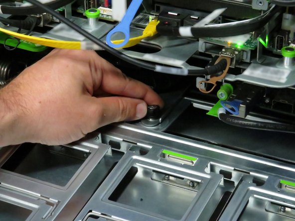
Press both tray release levers upwards.
-
Pushing the tray release handles inwards may assist in actuating the tray release levers.
-
Pull the two release handles that snap outward.
-
Slide the tray forward until fifteen hard disk drives can be seen.
-
-
-
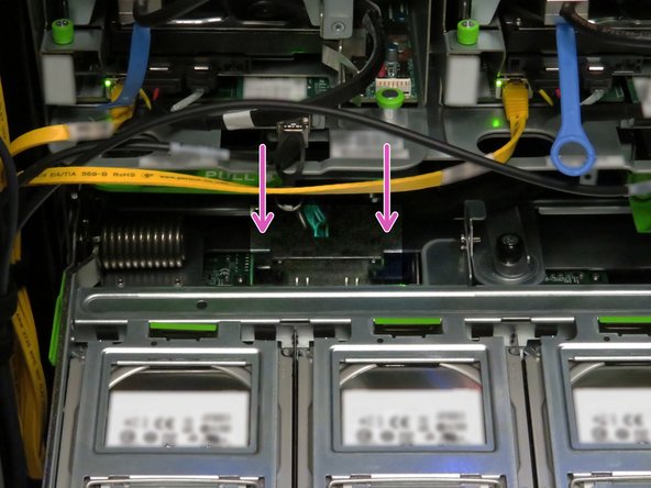
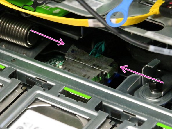
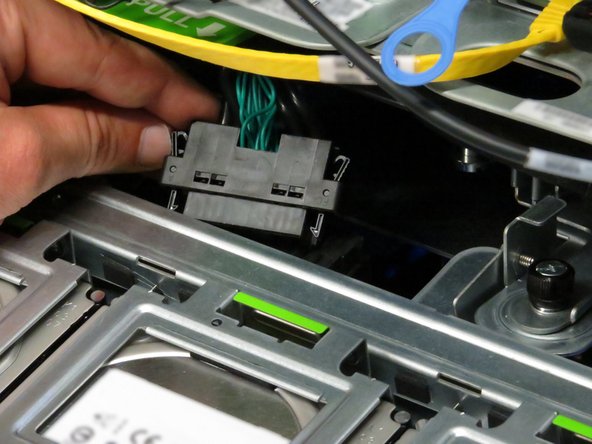
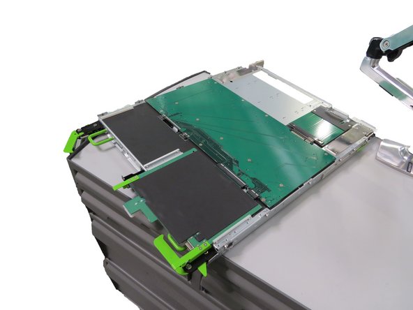
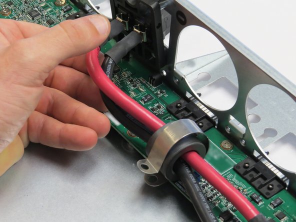
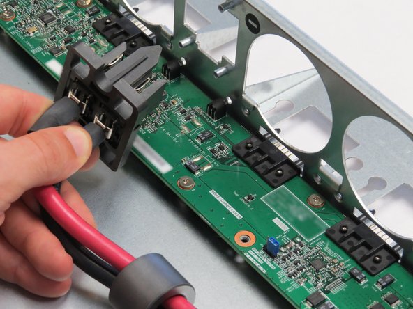
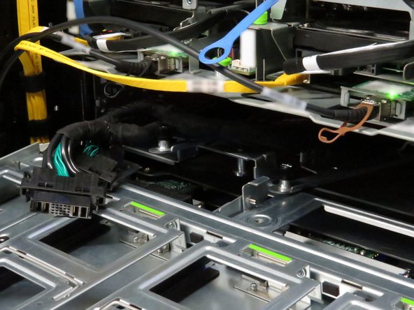
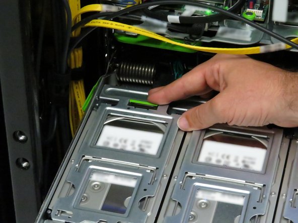
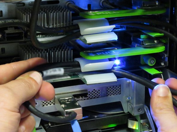
Press the two Powerblade cable retention tabs.
-
Pull the cable towards the rear until it unseats from its connector.
-
-
-
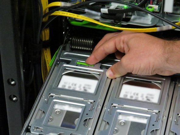
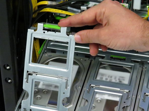
Open fifteen hard disk drive cages.
-
Press the green retention tab on the hard disk drive cage.
-
Rotate the cage to access the hard disk drive.
-
-
-
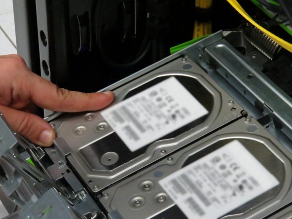
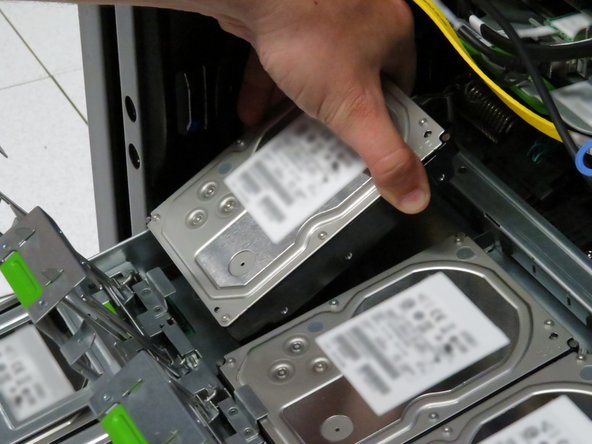
Push each hard disk drive away from the pivot point of each gate.
-
This will unseat the drives from their SATA and power connectors.
-
Remove each hard disk drive.
-
-
-
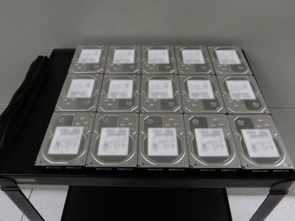
Place the hard disk drives on a work bench or cart.
-
It may be beneficial to rest the hard disk drives on an static-free mat to minimize risk of damaging the drives.
-
Because the drives will be reinstalled in the tray, it is beneficial to place them in a logical order to hasten their reinstall.
-
-
-
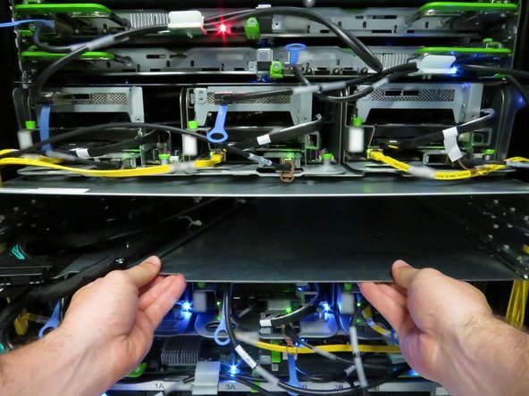
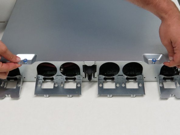
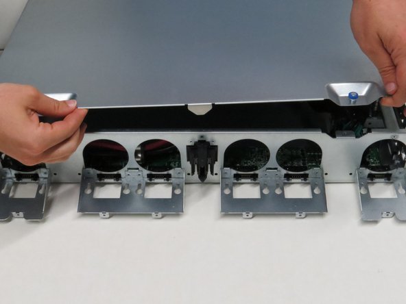
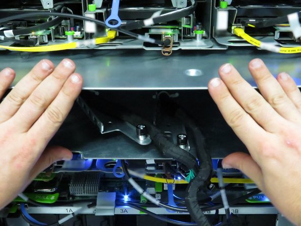
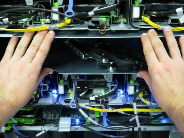
Press down two storage tray locking tabs.
-
The storage tray locking tabs are located towards the left-rear and right-rear of the tray.
-
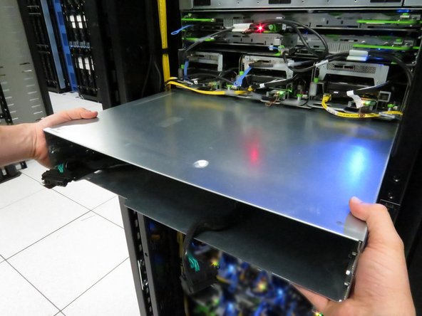
Pull the tray away from the Open Rack.
-
If depressing the tray locking tabs do not release the tray, push the tray into the chassis about 10cm. Extend the tray again until its about 5cm from its full extension. Press the locking tabs downwards and pull the tray.
-
-
-
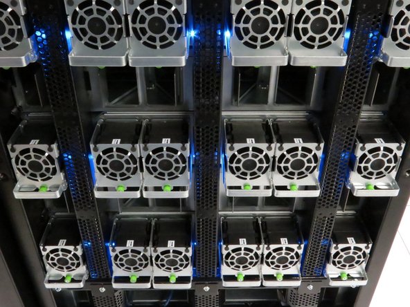
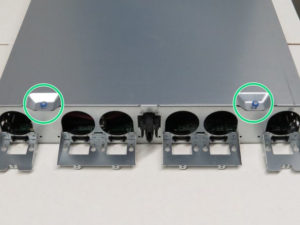
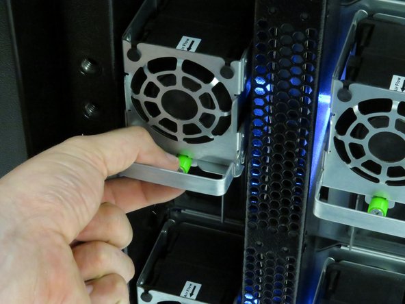
Remove the six chassis fans.
-
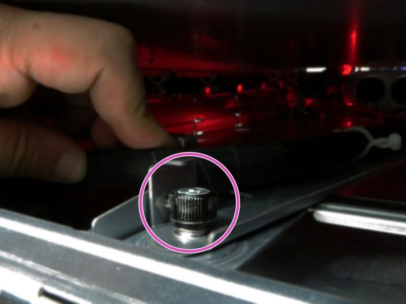
Unscrew the thumbscrew on each of the fans.
-
Grasp the fan handle and slide it to the rear. Lift the fan upwards.
-
-
-
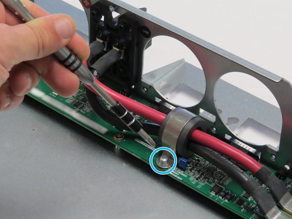
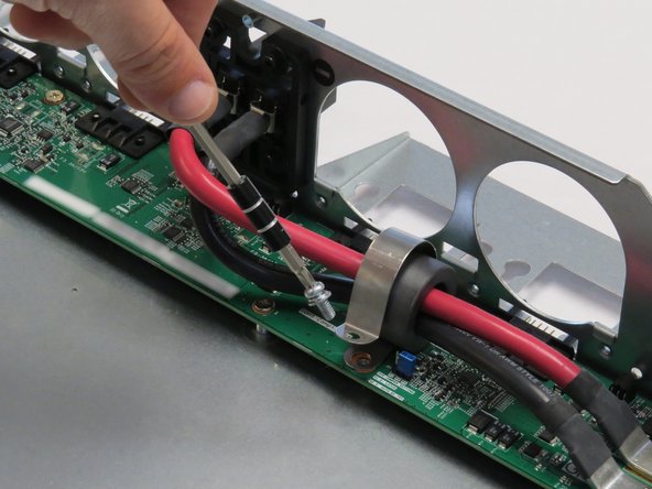
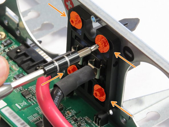
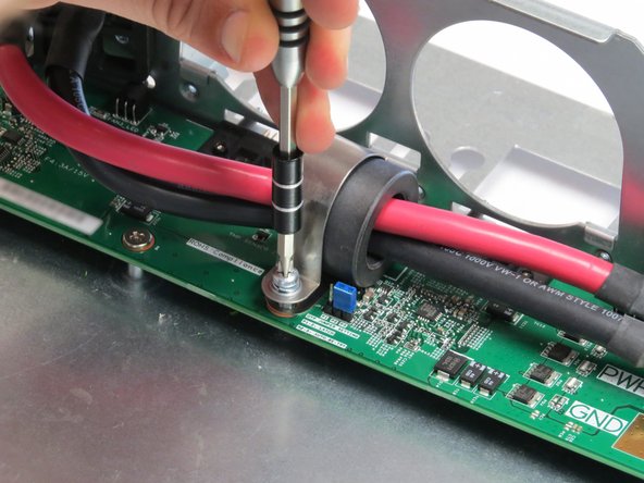
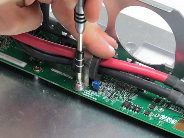
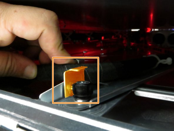
Unscrew one Phillips #2 screw securing the bus lead management clip to the fan controller board.
-
-
-
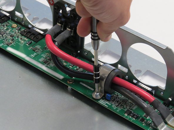
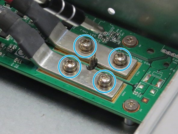
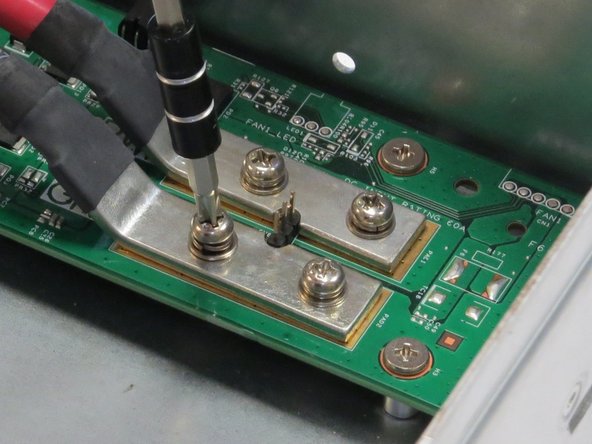
Unscrew four Phillips #2 screws that secure the bus bar leads to the fan controller board.
-
-
-
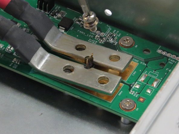
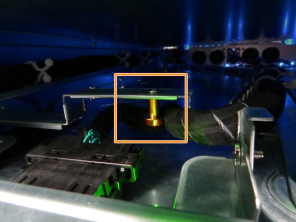
Insert a new bar clip into the chassis.
-
It is important to ensure that positive and negative lead polarity is oriented as indicated by the markings on the chassis, as annotated. Power polarity is indicated as follows:
-
PWR: (+)
-
GND: (-)
-


This work is licensed under a Creative Commons Attribution 4.0 International License.
This work is licensed under a Creative Commons Attribution 4.0 International License.

6 Comments
Classification, Design and accessories of Cable Tray:
Cable tray can be fabricated and design according to industrial usage and plant specifications; it could be in following types.
Ladder Cable tray:
A stair type ladder tray consists of Rungs which is joint by two sheet walls. It has relevantly less weight.
Perforated Cable tray:
Design, bend and fabricated a one piece of material and perforated by punches. It has high weight as compared to Ladder cable Tray.
Cable tray used for electrical cable distribution in the building’s structural plants and pipe racks, cable laying cable routing at cable tray also use for protection. Cable tray used for all control and power cables cable tray also use as mechanical protection of cable protect from falling off any object directly at the live cable, cable trays are manufactured of different types.
Cable ladder
Perforated cable tray
Cable duct
Cable Mesh
The types of cables, allowed in cable tray, and the wiring methods permitted in cable trays can be found in NEC Section 392.10 (A). This Section also lists various corresponding NEC Articles which describe the conditions of use and installation requirements for a particular class or type of cable. Additional considerations such as fill capacity, allowable ampacity, cable splicing within trays, and securing and supporting cables are addressed in Article 392. Users should be familiar with all these Articles and check the manufacturer’s specifications, to verify selected cables meet all application requirements and NEC requirements.
Cable tray use for cable managements to protect the cables and for proper dressing of cables. Cable tray use at almost all industry sizes and material selection will be different for every project cable tray material selection also depends on the process and indoor-outdoor usage and at cable types
Three major types of cable tray
1- Perforated cable tray
2- Ladder Type Cable tray
3- Wire mesh type cable tray
<a href="https://www.alfazalengineering.com/cable...>Cable Tray</a>
Alfazal Engineering providing services for '''''Cable tray''''', Tower tray, and other sheet metal work at very economical prices with the best delivery time all over Pakistan. tower trays for the refinery.
Cable Tray street lighting poles manufacturer in Pakistan by Al-Fazal Engineering
Perforated Cable Tray Made of Sheets With Perforation on the based. Cable Gland, Cable tray distributor in Pakistan. We are available for your support 24/7 and 100% guarantee for quality. We never compromise in quality.