
Introduction
Overview
This guide demonstrates how to replace the LED cable in an Open Compute V2 chassis. == Acronyms and Terms == * AC - Alternating Current * DC - Direct Current * LED - Light-Emitting Diode * PSU - Power Supply Unit * SATA - Serial ATA ** ATA - AT Attachment
-
-
Power off both server systems in the Open Compute V2 chassis.
-
Remote Power Down: Login to each server to power it off.
-
shutdown -h now;exit -
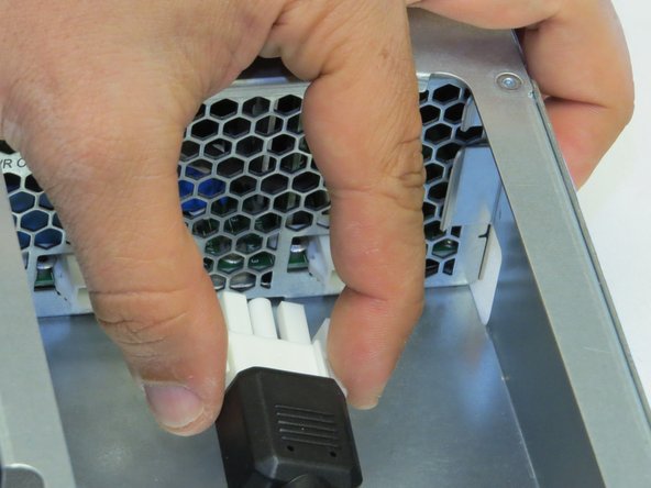
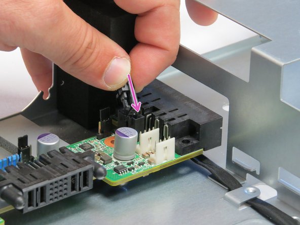
Hardware Power Down: Press and hold the power switch for at least three seconds, as annotated.
-
-
-
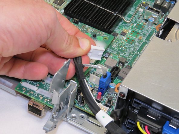
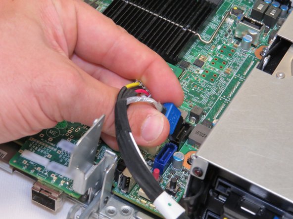
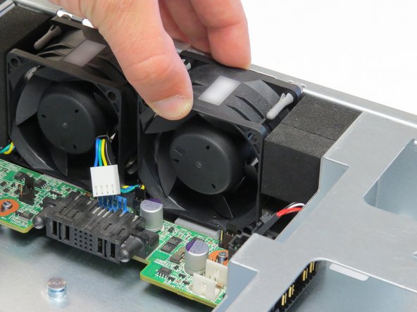
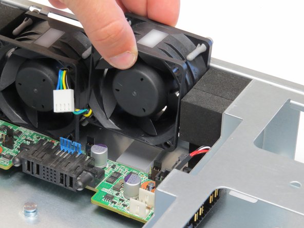
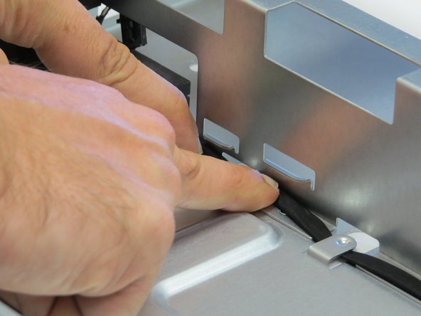
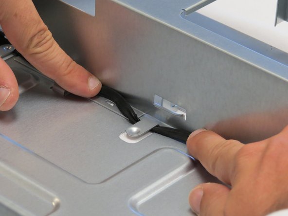
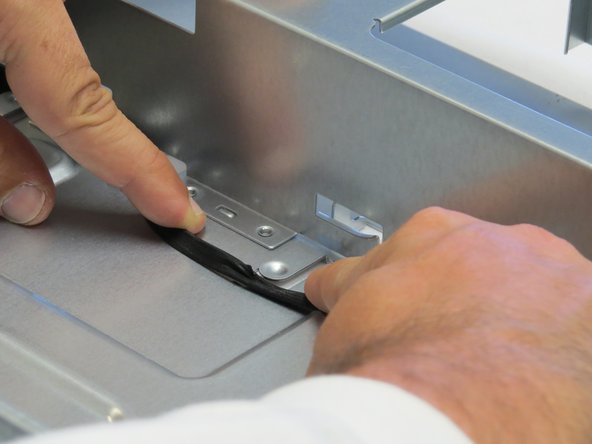
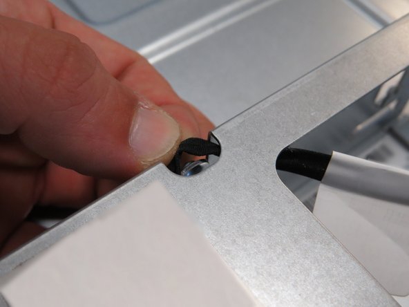
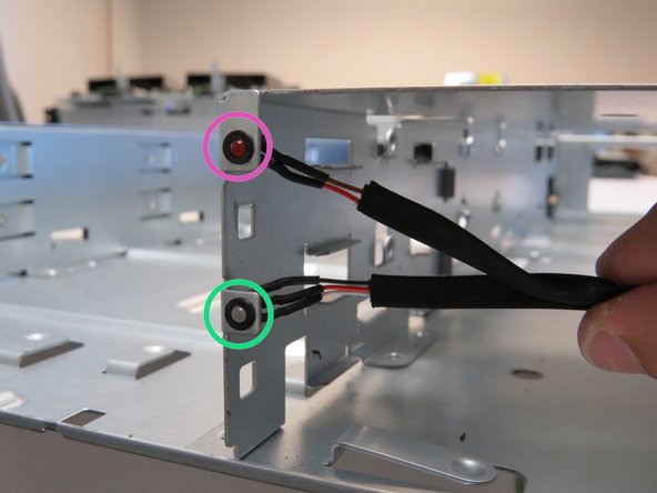
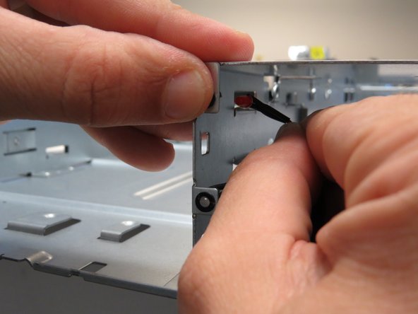
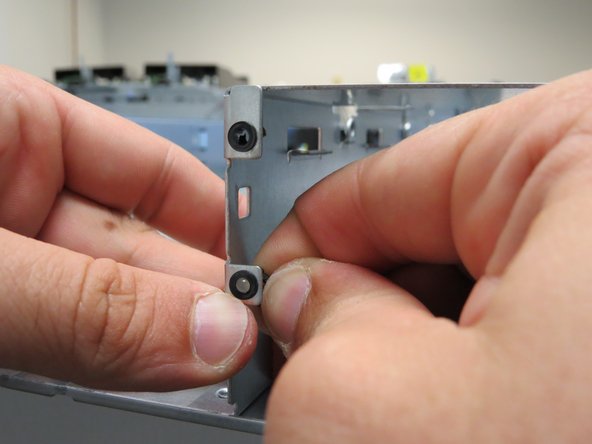
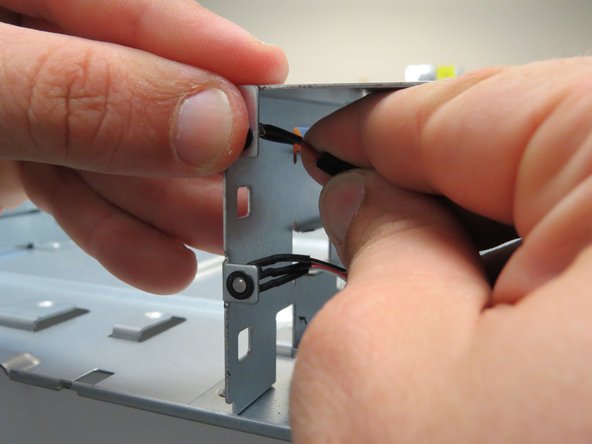
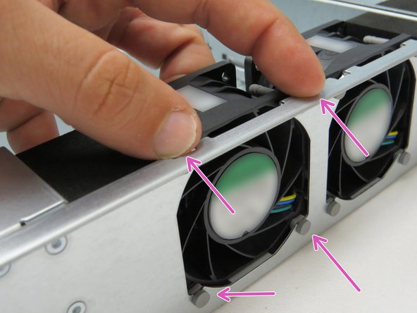
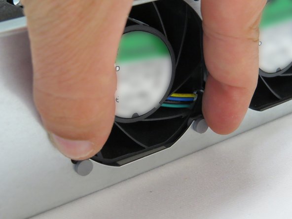
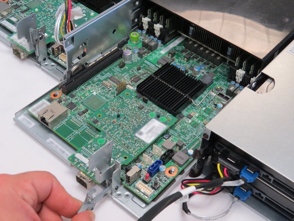
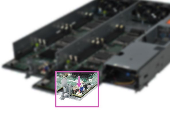
Place the LED bulbs into their chassis holders.
-
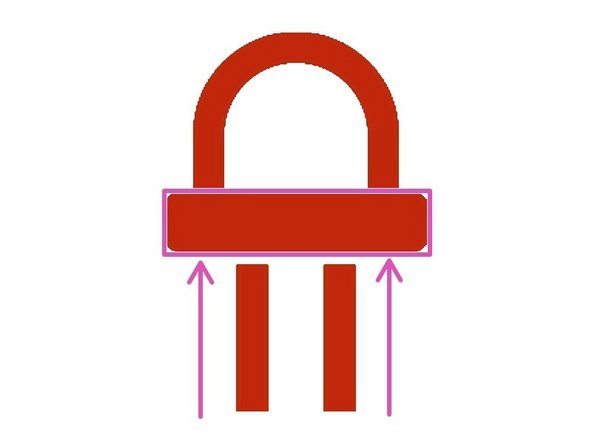
To avoid damaging the cable, apply force to the LEDs most near the bulb.
-
The LEDs will 'click' when positioned properly.
-
-
-
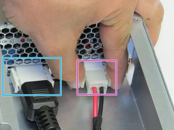
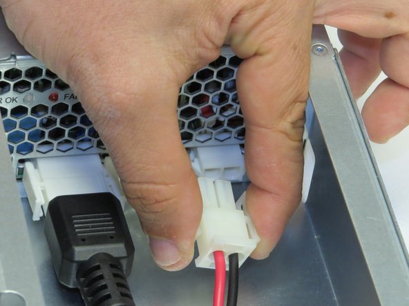
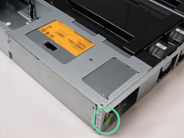
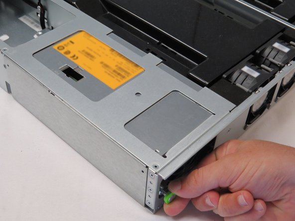
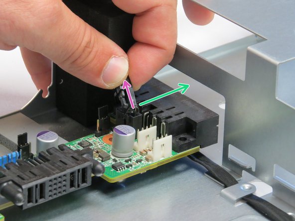
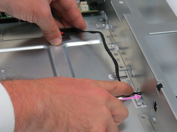
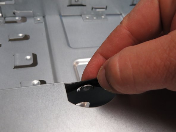
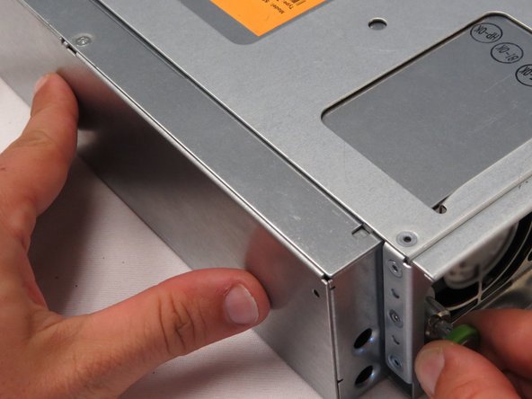
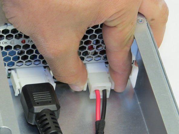
Pull the retention plunger away from the chassis.
-
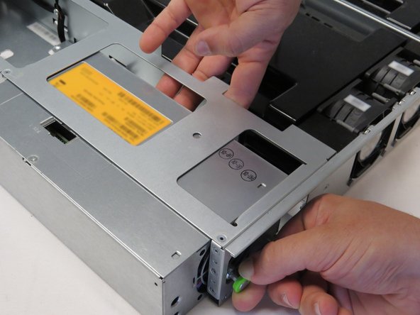
Release the retention plunger to secure the PSU.
-


This work is licensed under a Creative Commons Attribution 4.0 International License.
This work is licensed under a Creative Commons Attribution 4.0 International License.
