
Difficulty
Moderate
Steps
25
Time Required

Unnecessary Steps
This guide contains steps that are not necessary.
Introduction
This guide demonstrates how to replace the Central Processing (Processor) Unit (CPU) on the ORV1 Leopard server.
-
-
Perform a warm shut down on the server. Run:
-
ssh -l root <hostname> shutdown -h now
-
-
-
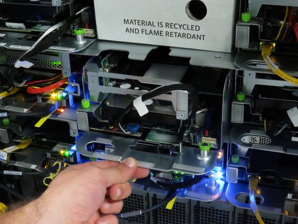
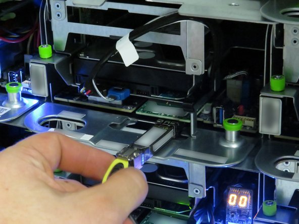
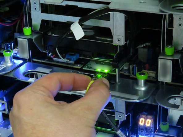
Disconnect the 10G network interface cable.
-
Pull the 10G network interface cable pull-tab.
-
-
-
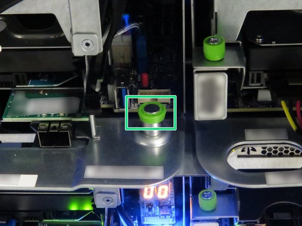
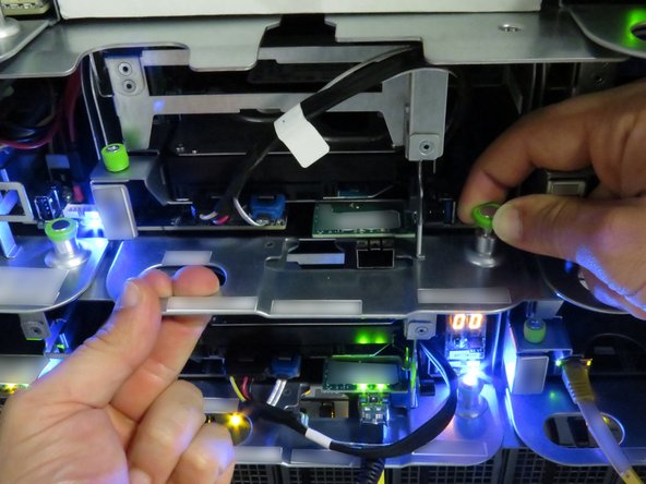
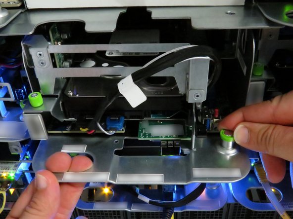
Pull the green retention plunger upwards.
-
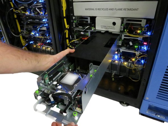
Pull the server away from the rack, as shown.
-
Pull the server until about (2) inches of the black lid is exposed.
-
-
-
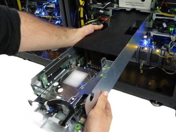
Move the server on the crash cart for transportation or out of rack repairs.
-
-
-
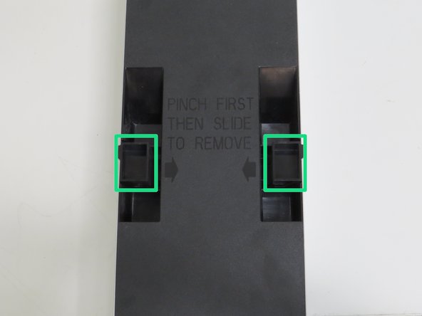
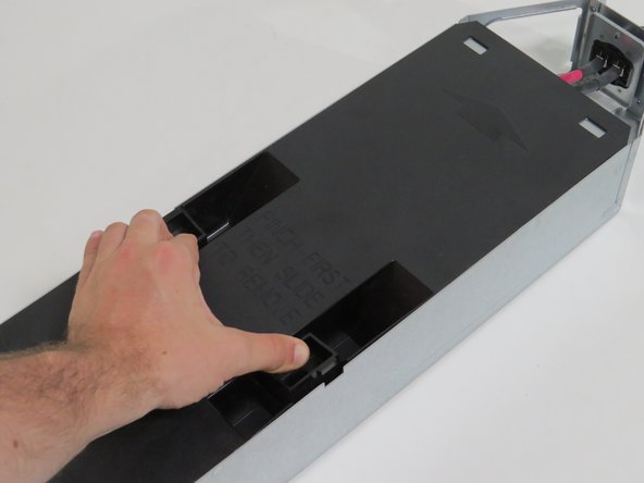
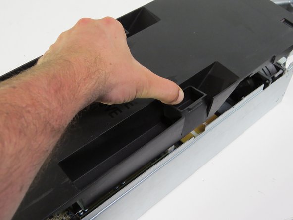
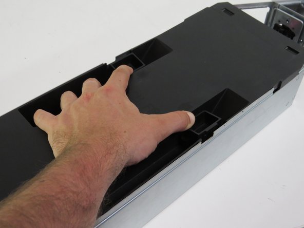
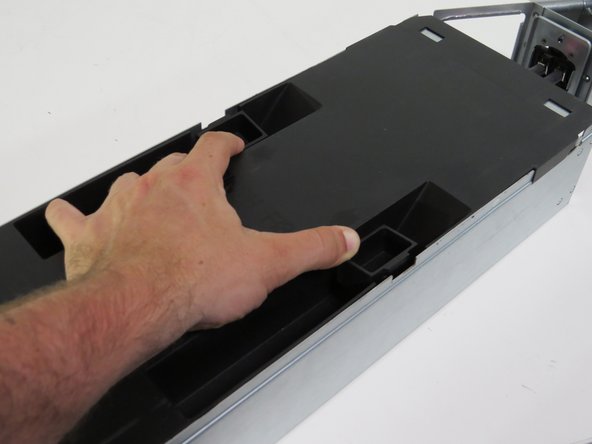
Squeeze (2) lid retention handles towards the center of the node.
-
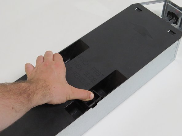
Slide the lid towards the rear of the server node.
-
Lift and remove the lid.
-
-
-
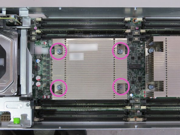
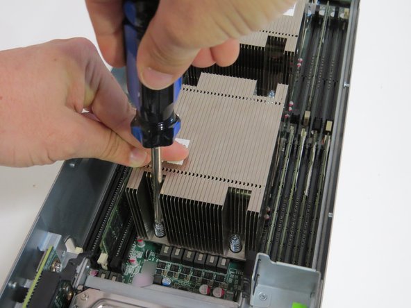
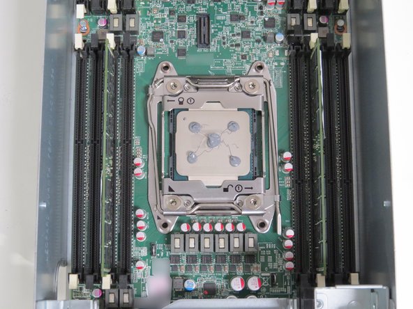
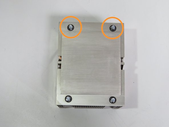
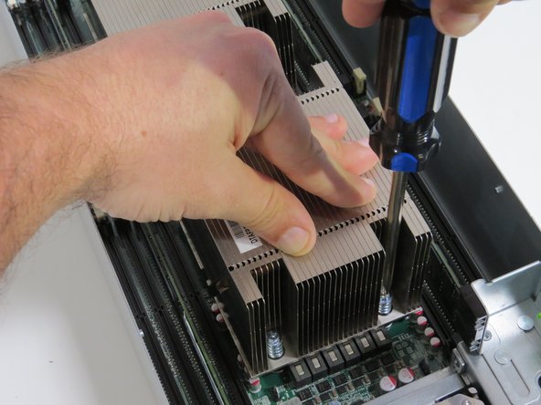
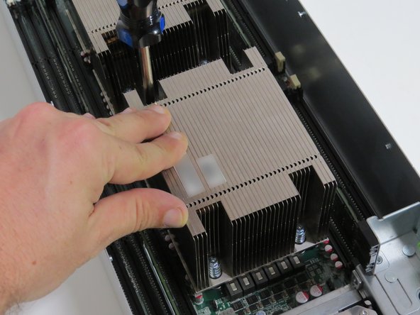
Loosen (4) torque screws with a Phillips #2 screwdriver.
-
Loosen screws in a diagonal sequence.
-
Loosen each screw halfway first (about two driver rotations). Proceed loosening the screws completely.
-
Use your hand to apply pressure to the corner nearest the screw being loosened.
-
-
-
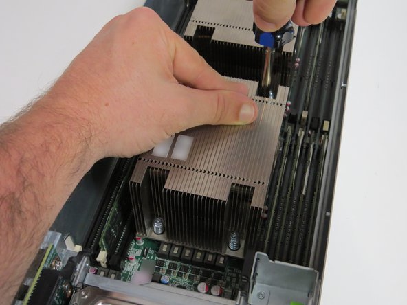
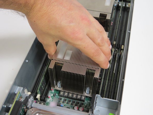
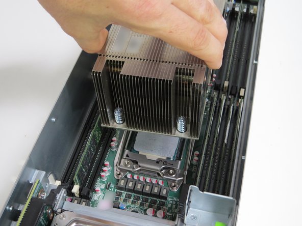
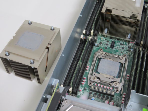
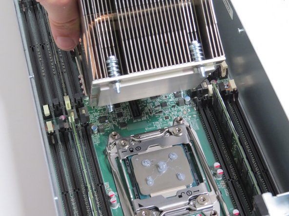
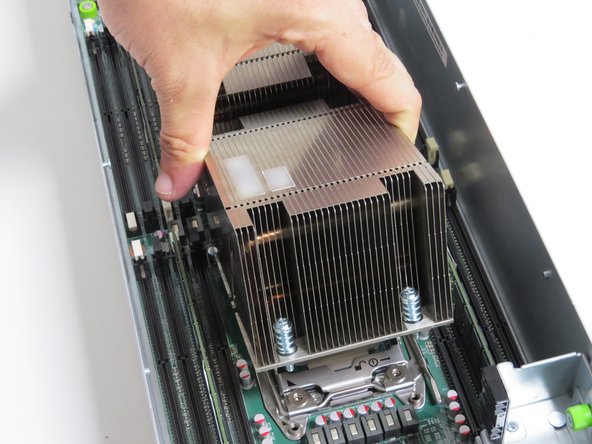
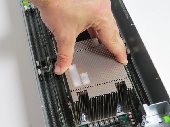
Lift the heatsink from the CPU socket.
-
Place the heatsink to the side of the server chassis, near its respective CPU socket.
-
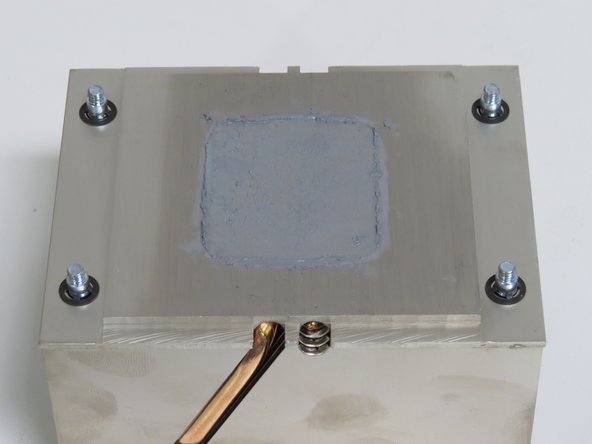
Make sure the heatsink is facing upwards (with the thermal compound exposed).
-
-
-
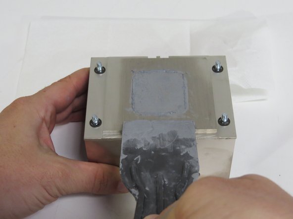
Scrape the thermal compound application from the heatsink using a plastic putty knife.
-
Scrape the thermal compound parallel to the machined grain, as shown.
-
-
-
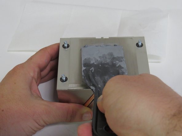
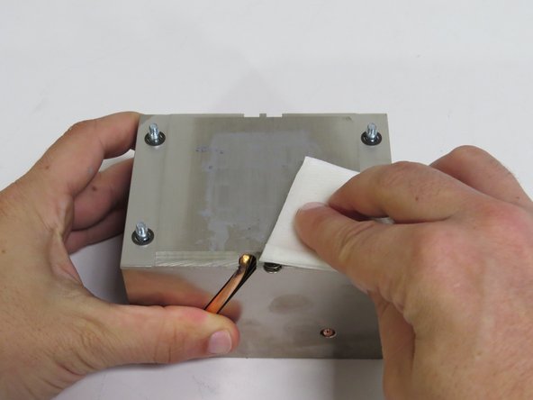
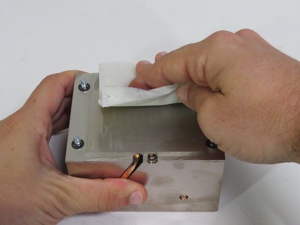
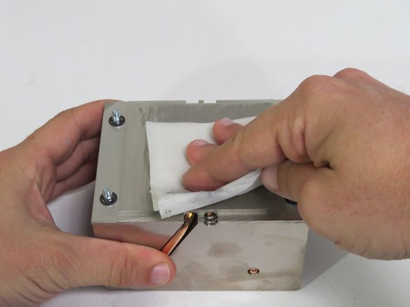
Wipe the remaining thermal compound off of the heatsink with an ispropyl alcohol pad.
-
Wipe the thermal compound parallel to the machined grain, as shown.
-
Continue this process until no thermal compound residue remains on the heatsink.
-
-
-
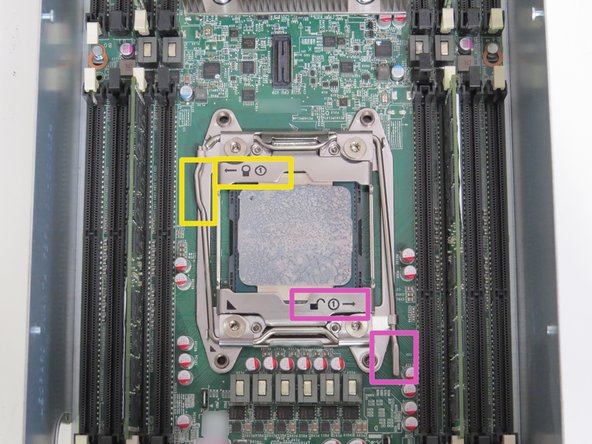
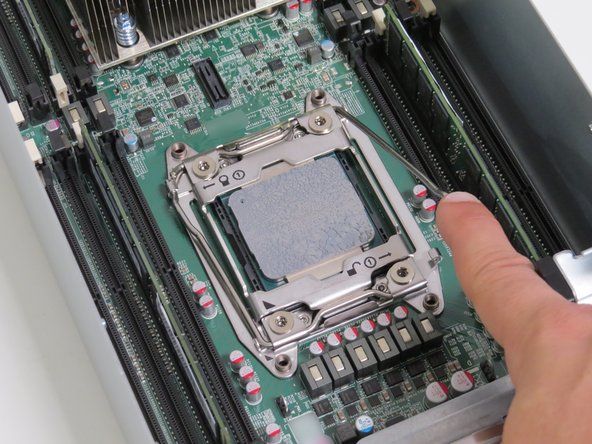
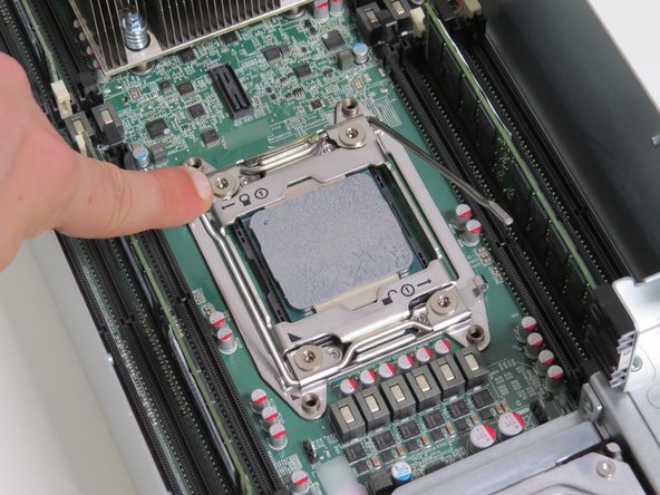
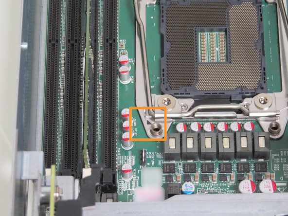
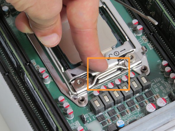
Unlatch (2) CPU retention release levers
-
Unlatch the 'unlock' retention lock first.
-
Unlatch the 'lock' retention lock second.
-
Press the retention rods down and push them towards the CPU. Allow the retention rods to slowly lift.
-
CPU retention release levers are spring loaded. Apply slight pressure as they lift to avoid injury and damage.
-
-
-
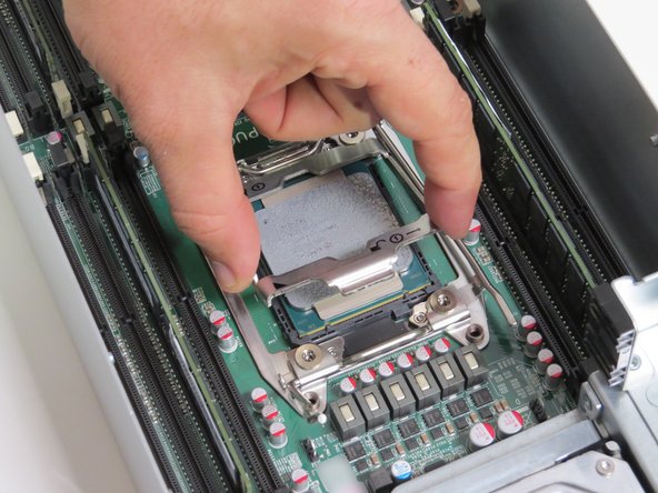
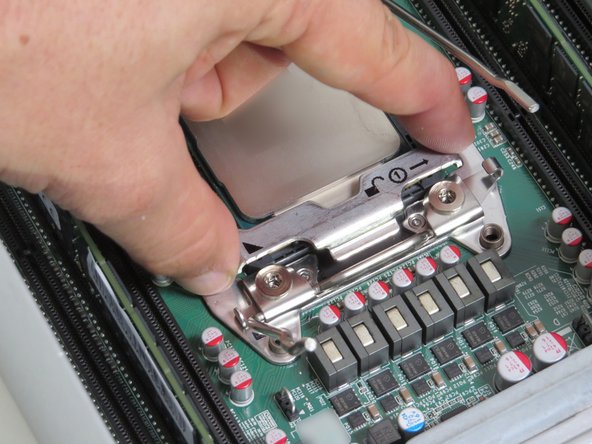
Lift the CPU retention bracket.
-
Allow the CPU retention bracket to pivot, and let stand vertically.
-
-
-
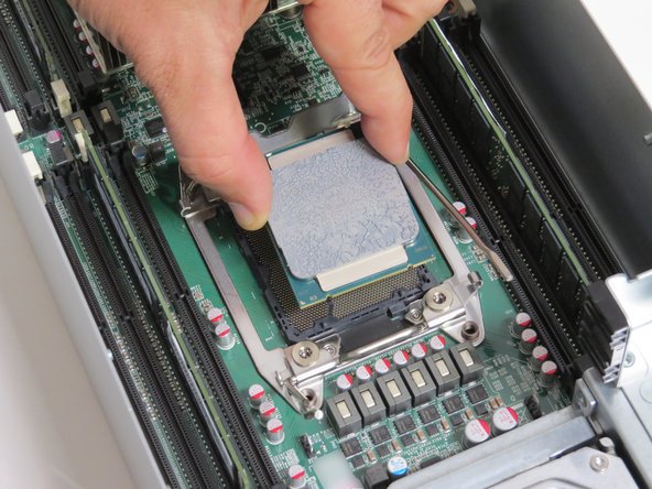
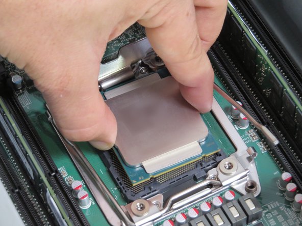
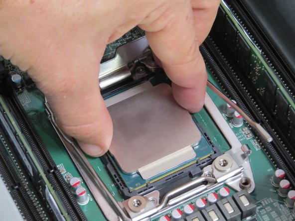
Grasp the CPU by its sides.
-
Lift the CPU from its socket.
-
-
-
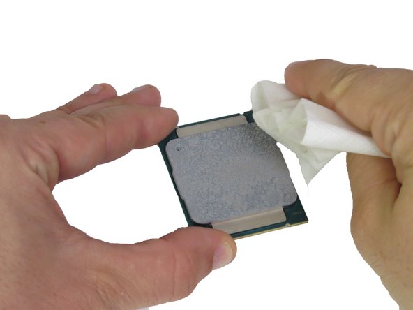
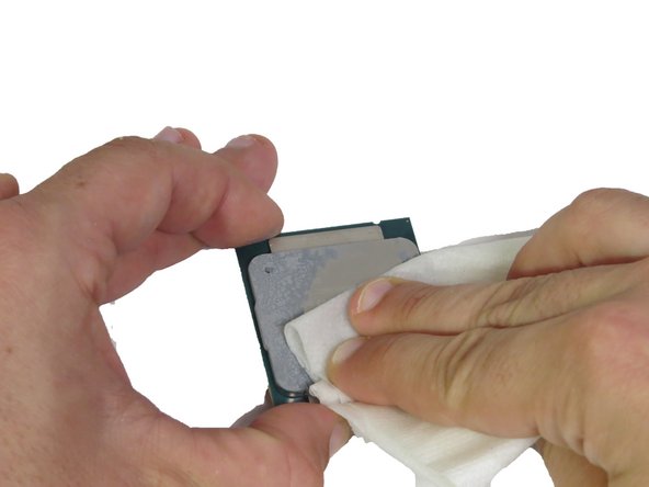
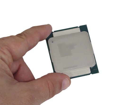
Wipe the top of the CPU with an ispropyl alcohol pad to remove the thermal compound residue.
-
Multiple passes may be needed. Continue until all the thermal compound residue has been removed.
-
-
-
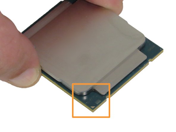
Orientate the CPU so that the arrow printed on the CPU aligns with the arrow printed on the CPU retention housing, as shown.
-
-
-
Lower the CPU directly onto its socket, as shown.
-
-
-
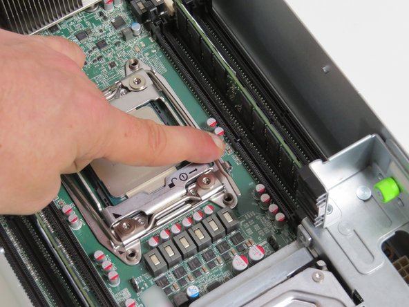
Close the CPU retention gate.
-
Ensure the 'lock' CPU retention lever is on top of the CPU retention gate lip, as shown.
-
-
-
Lock the CPU in its socket.
-
Close both retention levers. Close the 'lock retention lever first, and then the 'unlock' retention lever.
-
-
-
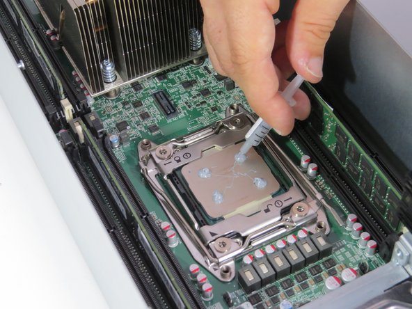
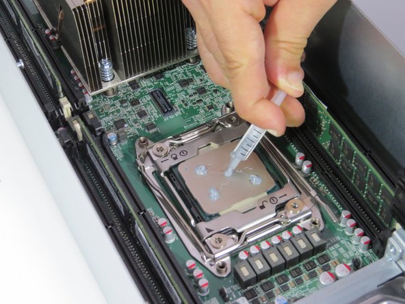
Apply thermal compound to the top of the CPU using the 5-dot method.
-
Place 0.2 grams of thermal compound on each CPU corner. Drag residue towards the center of the CPU.
-
Place 0.2 grams of thermal compound on the center of the CPU.
-
0.2 grams is 'about' 1 hash mark tick on the 1 gram CPU thermal compound syringe. Click here for more syringe tips and information.
-
-
-
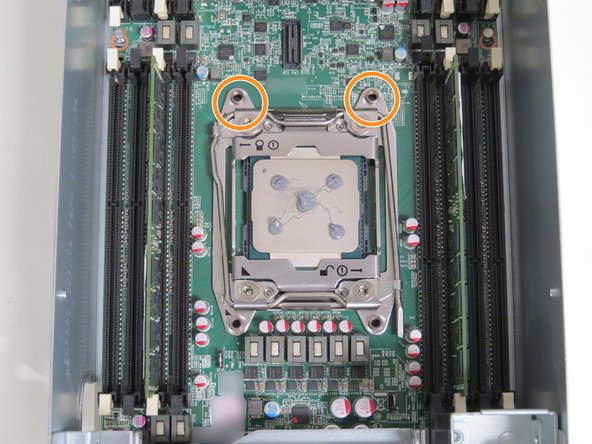
Align the rear (2) heatsink screw posts with the CPU retention post holes, as shown.
-
-
-
Lower the heatsink onto the CPU.
-
Pivot the heatsink forward so that the front two screw posts mate with the CPU retention post holes, as shown.
-
-
-
Tighten (4) torque screws using a Phillips #2 screw driver.
-
Tighten screws in a diagonal sequence.
-
Tighten each screw halfway first.(about two driver rotations). Then, proceed to tighten each screw completely.
-
-
-
Install the lid on the server, as shown.
-
-
-
Slide the server back into the rack.
-
Continue pushing the server until the server chassis pin secures the server.
-
A distinctive 'click' will be felt when the pin secures the server in the rack.
-
-
-
Connect the 10G network interface cable.
-
-
-
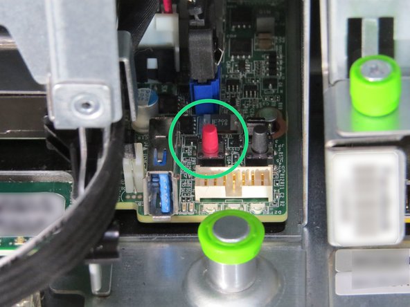
Press the power button.
-


This work is licensed under a Creative Commons Attribution 4.0 International License.
This work is licensed under a Creative Commons Attribution 4.0 International License.
