
Introduction
This guide demonstrates how to replace a central processing unit (CPU) in an Open Compute V3 server. == Acronyms and Terms == * CPU - Central Processing Unit * SFP+ - Enhanced Small Form-factor Pluggable; a type of hot-plug transceiver
-
-
The server can be powered off remotely or on the hardware itself.
-
Remote Power Down: Login to the server to power it off.
-
shutdown -h now;exit -
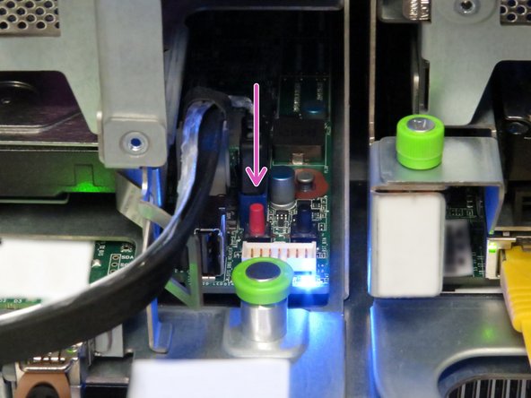
Hardware Power Down: Press and hold the power switch for at least three seconds, as annotated.
-
-
-
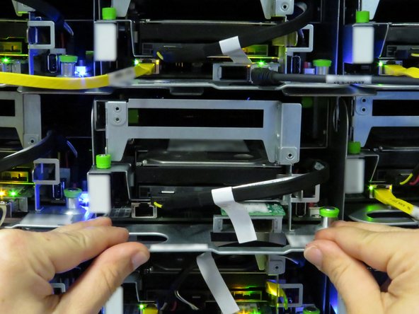
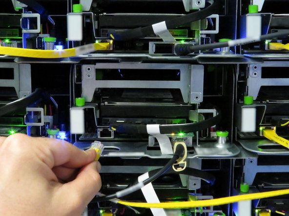
Disconnect the Ethernet cable from the server.
-
Press the tab on the end of the cable to release it.
-
-
-
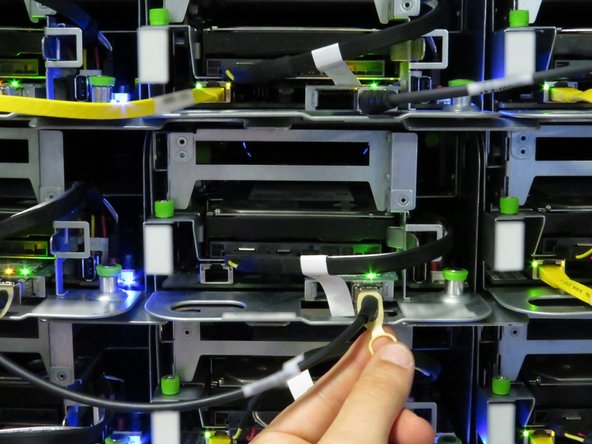
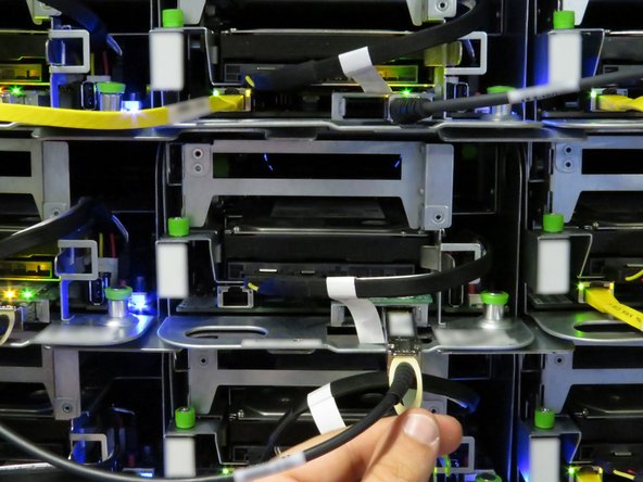
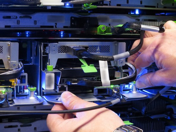
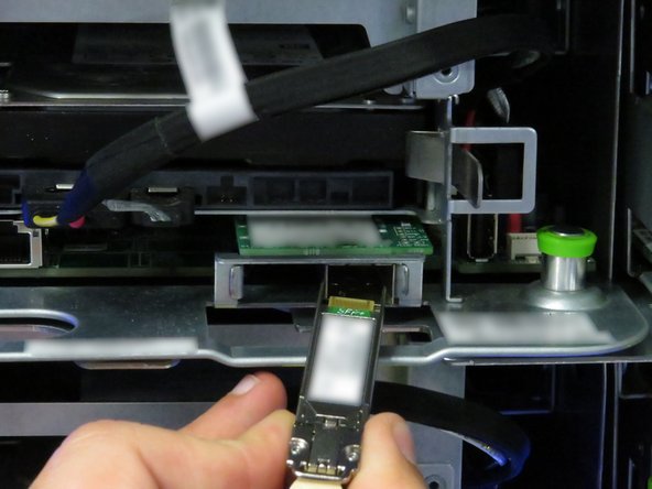
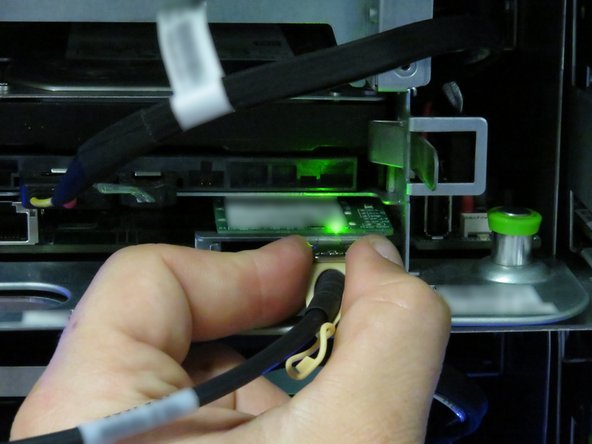
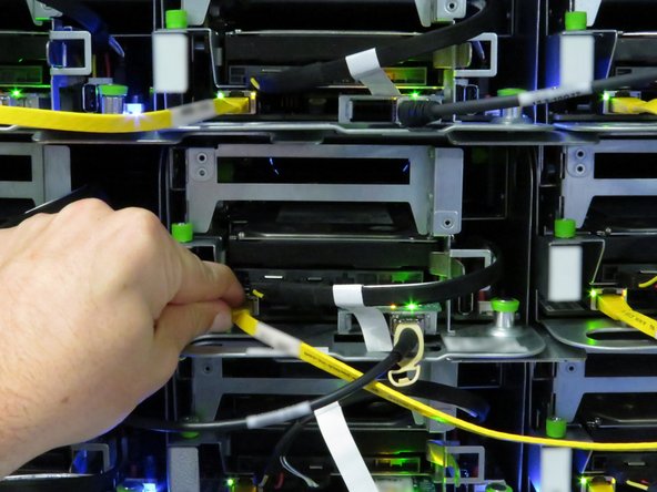
Disconnect the 10G SFP+ cable from the network interface controller.
-
Use the pull-tab to disconnect the cable.
-
-
-
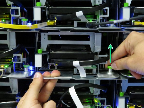
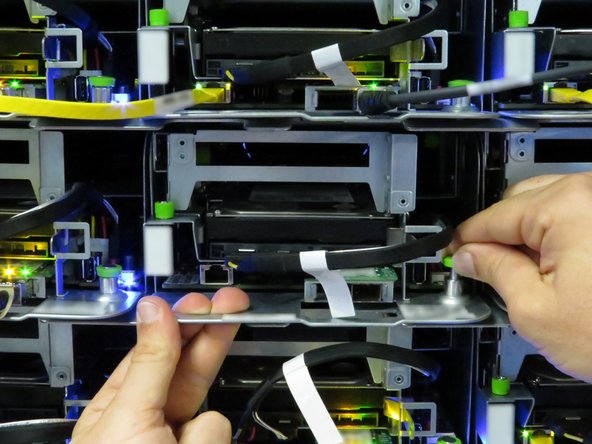
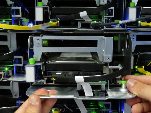
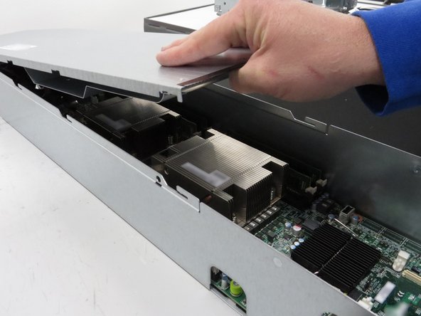
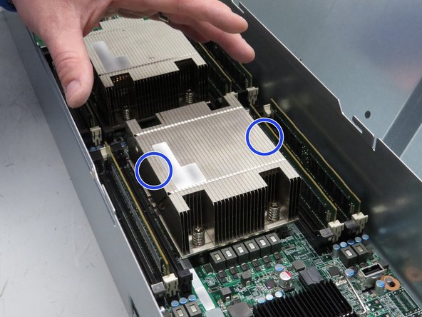
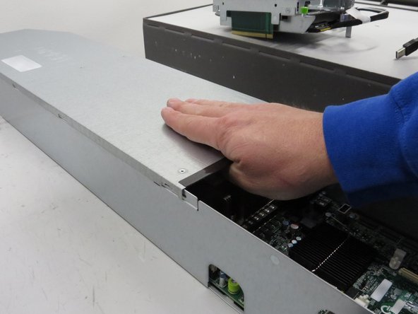
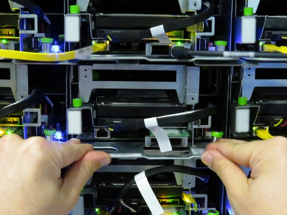
Grasp the server as shown.
-
Pull the retention plunger upwards.
-
Begin sliding the server out of the rack.
-
-
-
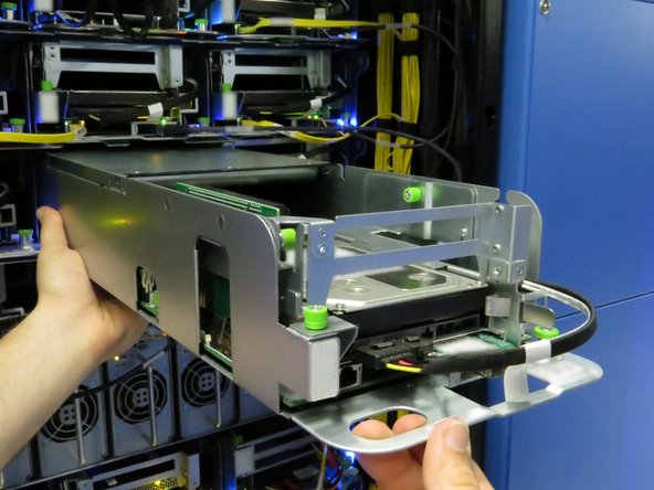
Counter the weight of the server, as shown.
-
Completely remove the server from the rack.
-
-
-
Slide the server into the rack.
-
The retention plunger does not need to be pulled upward during installation.
-
The server is secure when the retention plunger snaps shut.
-
-
-
Connect the 10G SFP+ cable into the network interface controller.
-


This work is licensed under a Creative Commons Attribution 4.0 International License.
This work is licensed under a Creative Commons Attribution 4.0 International License.

2 Comments
If you’re looking to get Philo on your Samsung Smart TV, you’re in luck! In this guide, we’ll walk you through the process of adding Philo to your Samsung Smart TV. Whether you’re a new user or an experienced one, this guide will be helpful for you. So, let’s get started!
Such a great explanation with images. Thanks for sharing with us. If you need any information about the monitors, visit here - 4videoequipment
Aali Mehra - Resolved on Release Reply