
Introduction
Overview
This guide demonstrates how to replace a central processing unit (CPU) in an Open Compute V2 server. == Acronyms and Terms == * CPU - Central Processing Unit * DIMM - Dual In-line Memory Module * SATA - Serial ATA; a type of computer bus interface * SFP+ - Enhanced Small Form-factor Pluggable; a type of hot-plug transceiver
-
-
The server can be powered off remotely or on the hardware itself.
-
Remote Power Down: Login to the server to power it off.
-
shutdown -h now;exit -
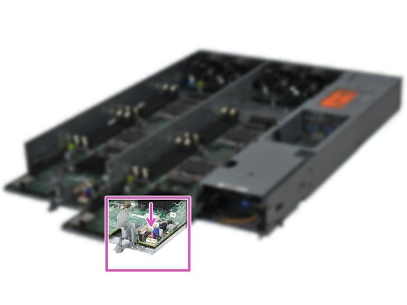
Hardware Power Down: Press and hold the power switch for at least three seconds, as annotated.
-
-
-
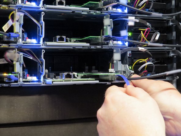
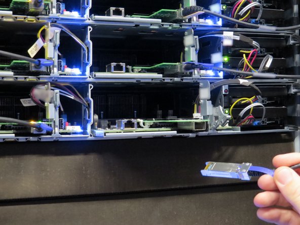
Disconnect the 10G SFP+ cable from the network interface controller.
-
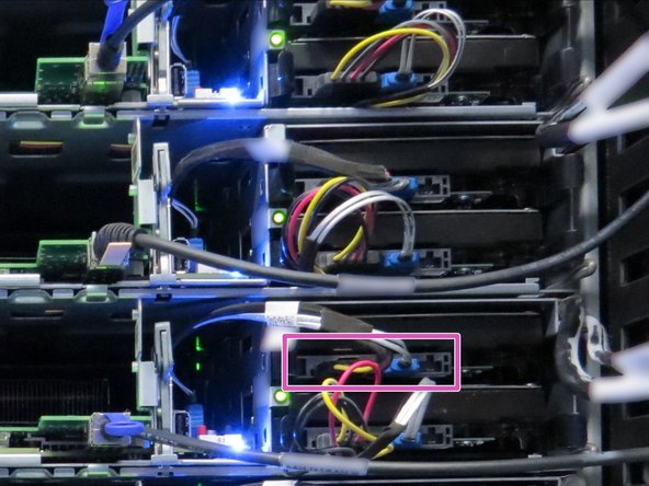
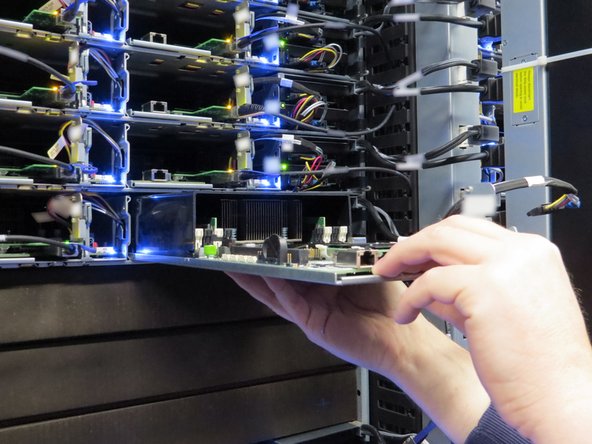
Disconnect the SATA / power cables connected to the boot hard disk drive.
-
Node 1 (right-most sled) boot drive is the top drive in the chassis. Node 0 (left-most sled) boot drive is the bottom drive in the chassis.
-
Disconnecting the SATA / power cable can be performed on either the motherboard or HDD end of server node 1 . However, the SATA / power cable must be disconnected from the motherboard end on node 0.
-
-
-
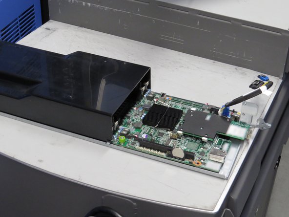
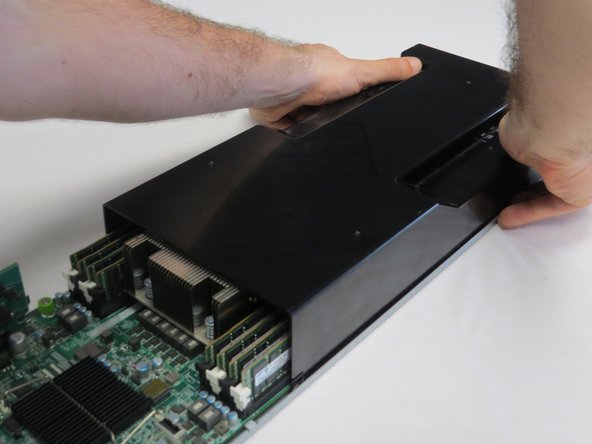
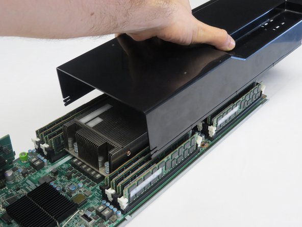
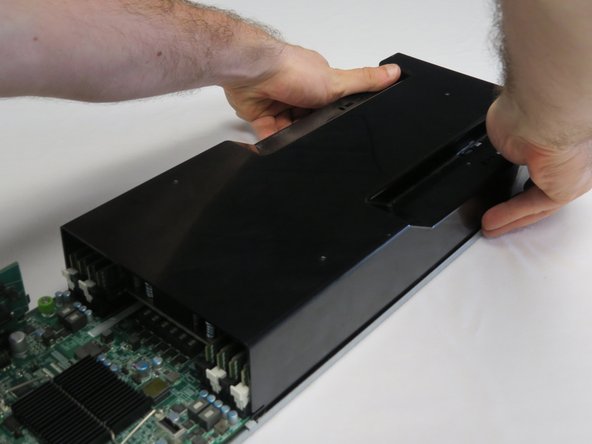
Remove the lid from the server node.
-
Engage the lid with both hands, as shown.
-
Push the lid towards the rear of the server.
-
Lift the lid.
-
-
-
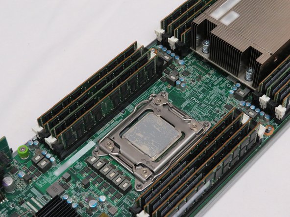
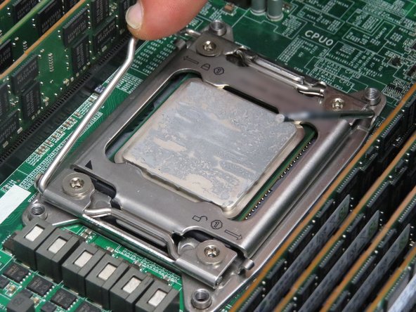
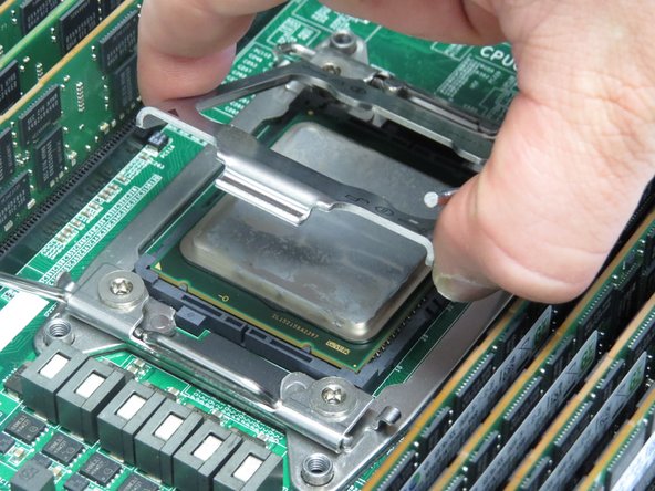
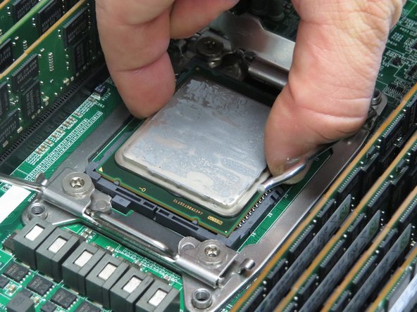
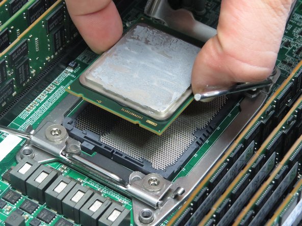
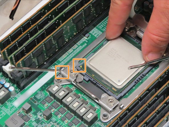
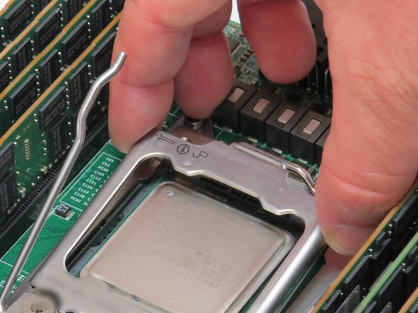
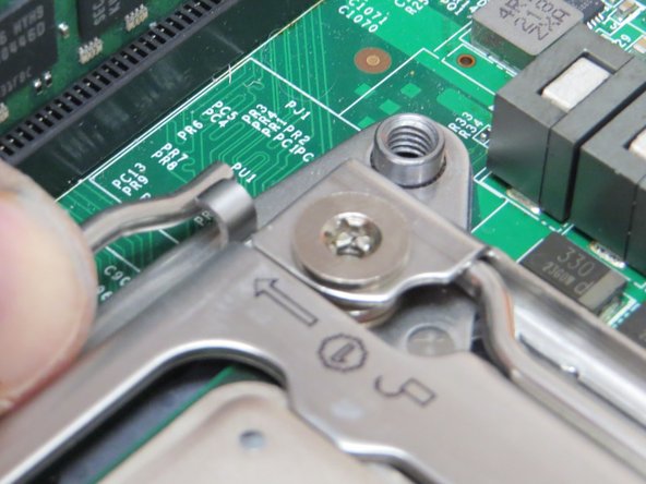
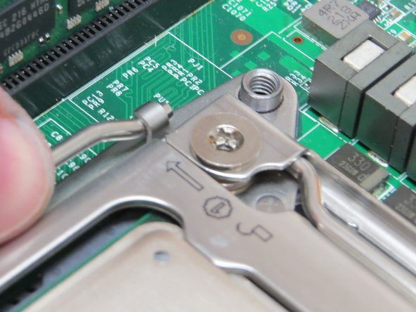
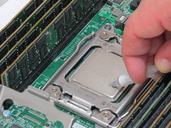
Align the arrow printed on the CPU with the arrow on the CPU retention bracket.
-
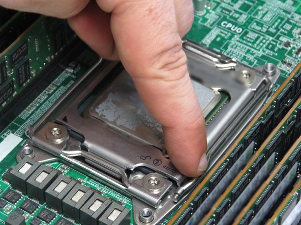
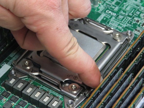
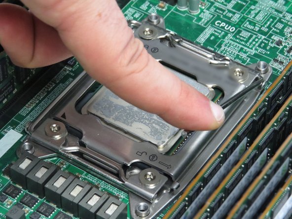
Seat the CPU in the socket.
-
Be careful when lowering the CPU into the socket. Mishandling the CPU can bend the LGA socket pins.
-
-
-
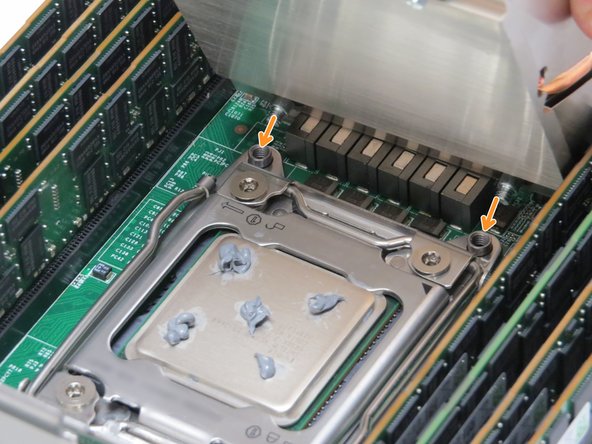
Apply thermal compound to the CPU, as shown.
-
About 1 gram of thermal compound should be distributed evenly in five dots.
-
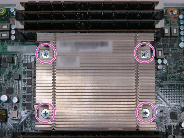
Align two heatsink posts with two holes in the CPU housing bracket, as annotated.
-
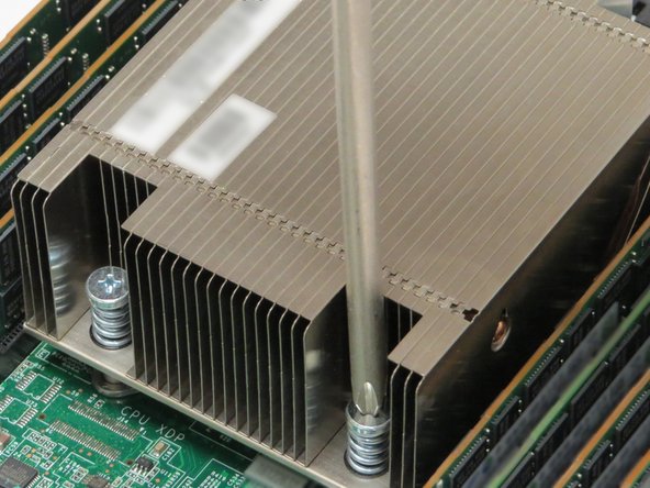
Pivot the heatsink so that all four screws are seated in the CPU housing bracket holes.
-
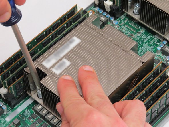
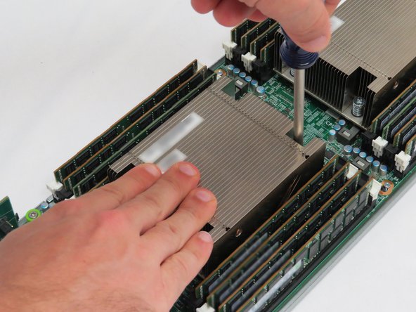
Tighten the four screws on the heatsink.
-


This work is licensed under a Creative Commons Attribution 4.0 International License.
This work is licensed under a Creative Commons Attribution 4.0 International License.
