
Introduction
This guide describes how to replace a DC Power Delivery Unit in an Open Rack V2.
-
-
Unseat all of the Battery Backup Units (BBUs) in both power shelves . There are three in each shelf and six total per rack. This reduces the risk of electric shock.
-
-
-
Identify if there are two plugs per rack or one plug per rack.
-
You should be able to see two cords coming from the top of the AC PDU with the text 'TOP SHELF' and 'BOTTOM SHELF'.
-
The plug with the white color under the three-phase AC plug is for the top shelf.
-
-
-
Turn off the breaker above the rack.
-
Some racks may have two plugs per rack and one plug per each power shelf. If this is the case, both breakers will need to be turned off.
-
-
-
Unplug the three-phase AC plug from the tap box.
-
-
-
Ensure that the green LED on the rear of the power shelf is not illuminated. A lit LED indicates 12V power from the bus bar.
-
If the 12V LED is not powered on, this indicates that there is no voltage on the rack bus bar. This will ensure a technician's safety when changing PDUs.
-
-
-
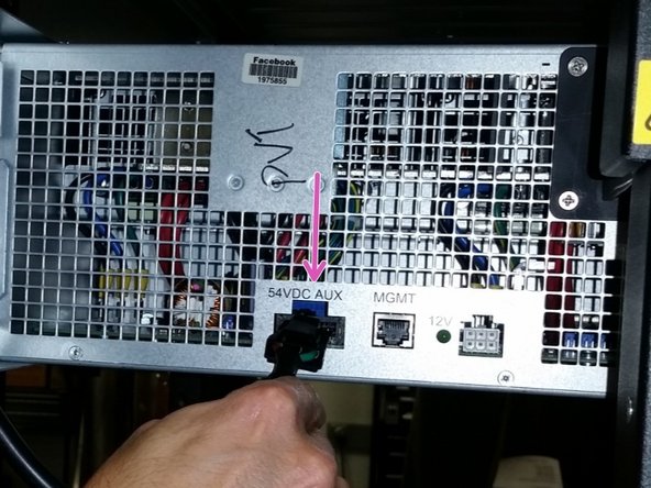
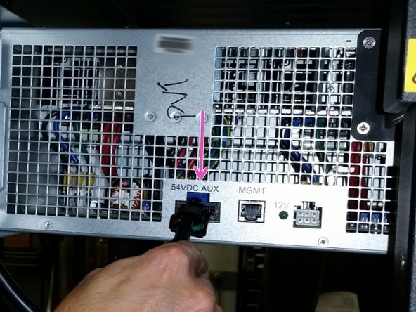
Unplug the 3-pin connector from the back of each shelf.
-
'54V AUX' is the label on the power shelf.
-
-
-
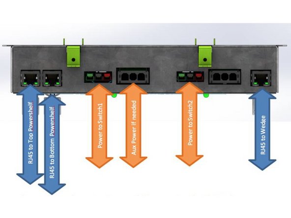
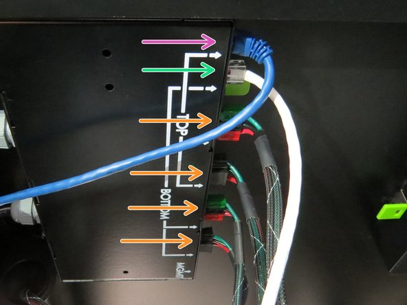
Remove any cables that are connected to the DC PDU.
-
-
-
Unlatch the two green tabs on the PDU from the top of the rack and remove the PDU.
-
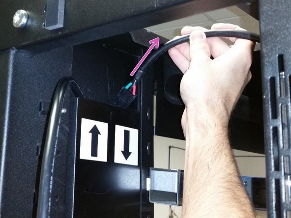
Guide the DC input power connectors into the side channels, then pull the cables out of the rack from the top.
-
-
-
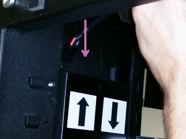
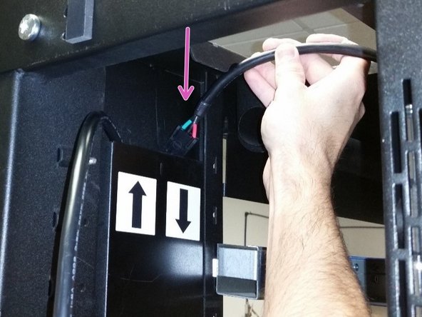
Insert the shorter 3-pin DC power cable into the trough with the arrow facing up (for the upper power shelf).
-
-
-
Insert the longer 3-pin DC power cable into the trough with the down arrow (for the lower power shelf).
-
Ensure that both DC power cables are fully inserted and are able to reach their corresponding power shelf.
-
-
-
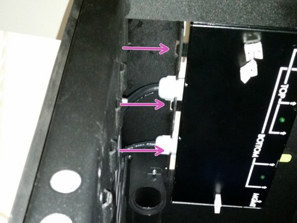
Align the three DC PDU tabs with the slots on the roof of the rack.
-
-
-
Apply upward pressure to the bottom of the PDU until the two green latches are depressed by the roof of the rack.
-
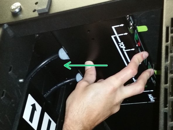
Slide the PDU towards the trough until the green latches snap into position.
-
-
-
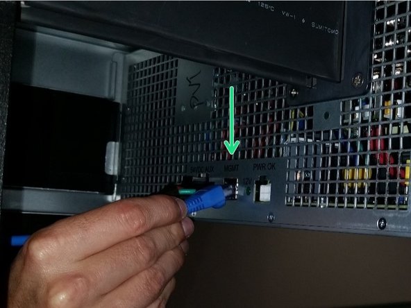
Feed both the blue and white Ethernet cables into the trough to their corresponding power shelf.
-
-
-
Connect each 3-pin DC power connector to their 54VDC AUX ports.
-
Connect each Ethernet cable to their management ports (these are labeled 'MGMT').
-
-
-
Connect the three-phase AC connector into the tap box.
-
Turn on the breaker.
-
Insert the BBUs back into the power shelf and the PSU LED should illuminate green.
-




This work is licensed under a Creative Commons Attribution 4.0 International License.
This work is licensed under a Creative Commons Attribution 4.0 International License.
