
Introduction
Overview
This guide demonstrates how to replace a drive plane board in an Open Compute V3 server. == Acronyms and Terms == * DPB - Drive Plane Board * SAS - Serial Attached SCSI
-
-
The server can be powered off remotely or on the hardware itself.
-
Remote Power Down: Login to the server to power it off.
-
shutdown -h now;exit -
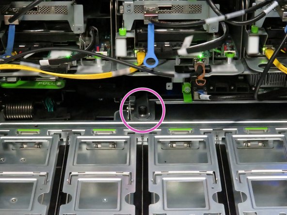
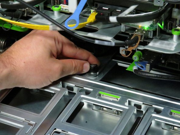
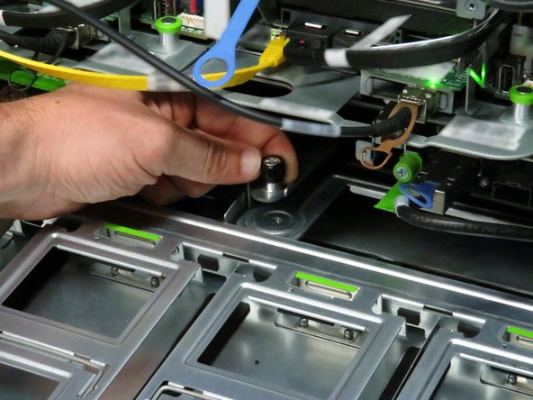
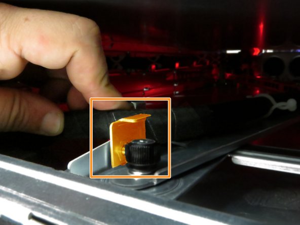
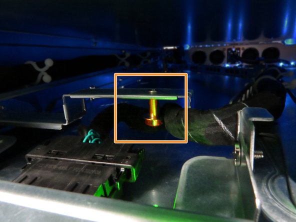
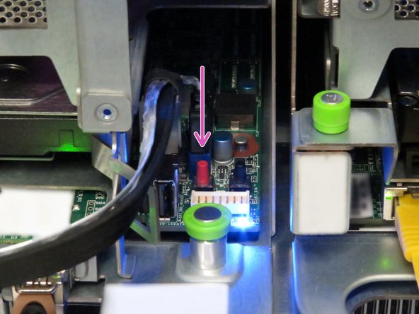
Hardware Power Down: Press and hold the power switch for at least three seconds, as annotated.
-
-
-
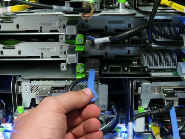
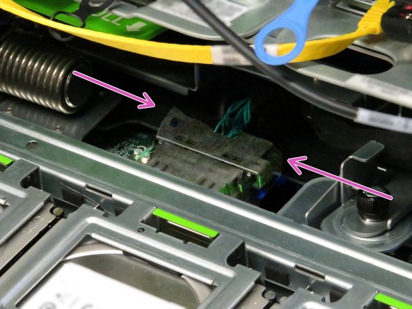
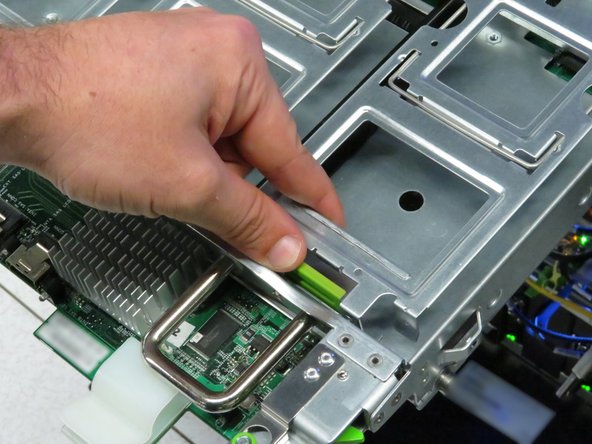
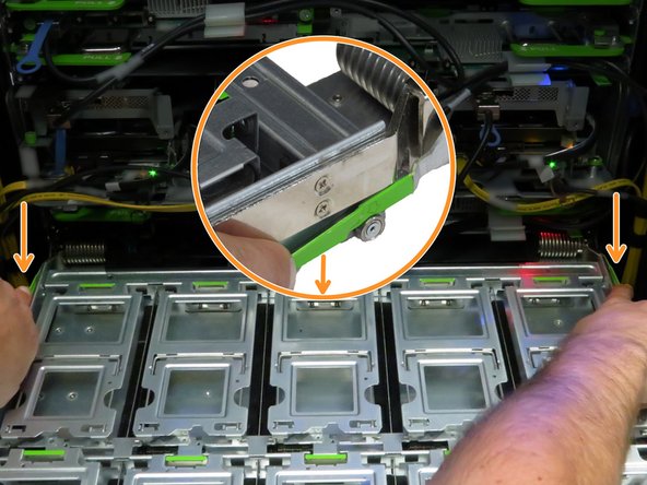
Disconnect the Mini-SAS cable from the storage tray.
-
Use the pull-tab to disconnect the cable, as shown.
-
-
-
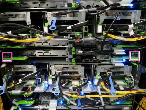
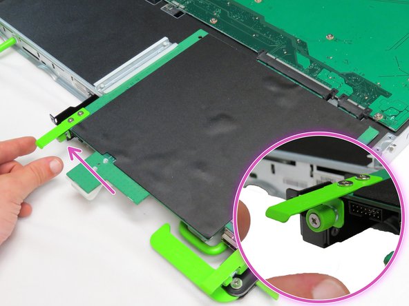
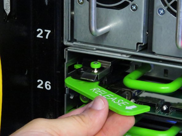
Locate the two tray release levers.
-
These release levers secure the tray to the storage chassis.
-
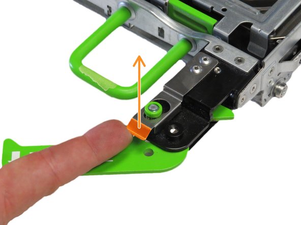
Press both tray release levers upwards.
-
Pushing the tray release handles inwards may assist in actuating the tray release levers.
-
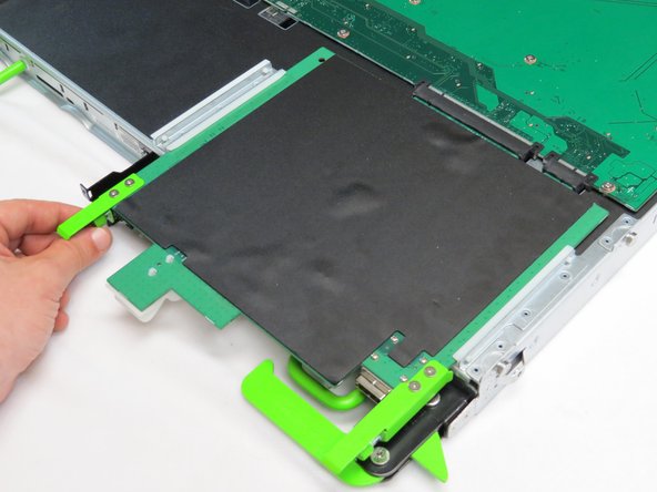
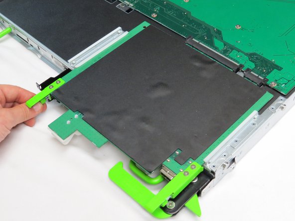
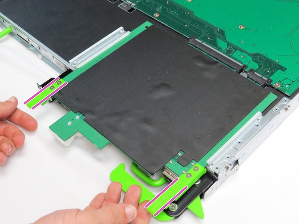
Pull the two release handles that snap outward.
-
Slide the tray forward until fifteen hard disk drives can be seen.
-
-
-
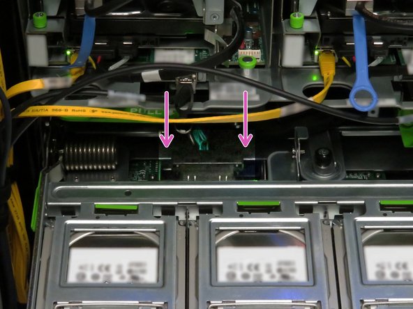
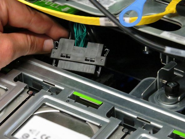
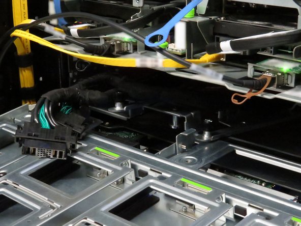
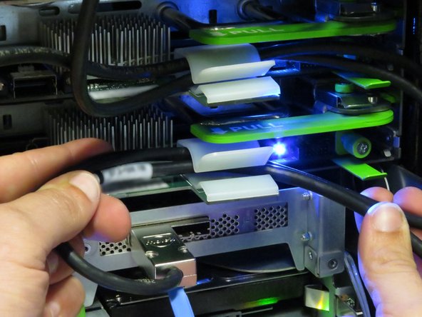
Press the two Powerblade cable retention tabs.
-
Pull the cable towards the rear until it unseats from its connector.
-
-
-
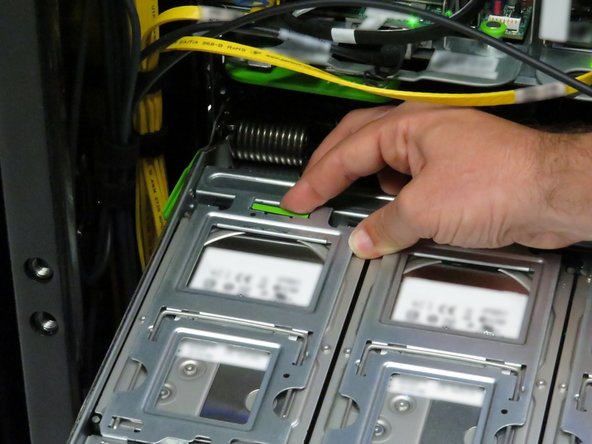
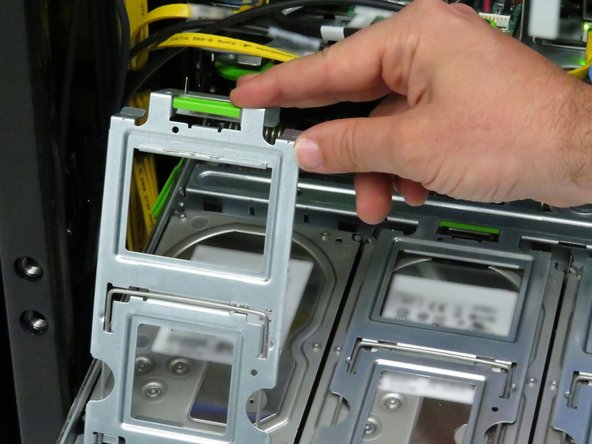
Open fifteen hard disk drive cages.
-
Press the green retention tab on the hard disk drive cage.
-
Rotate the cage to access the hard disk drive.
-
-
-
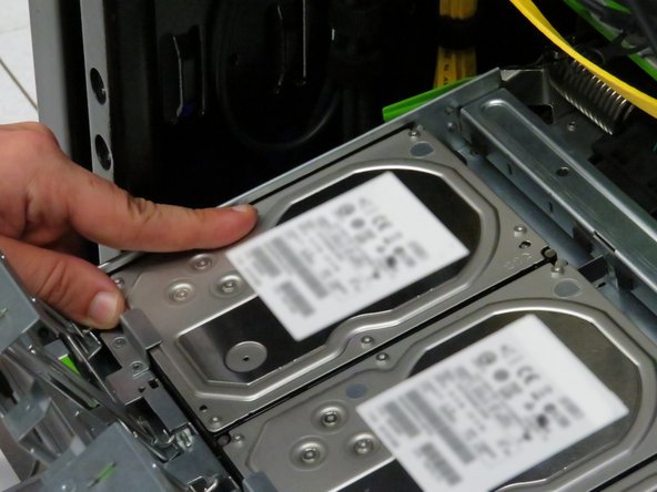
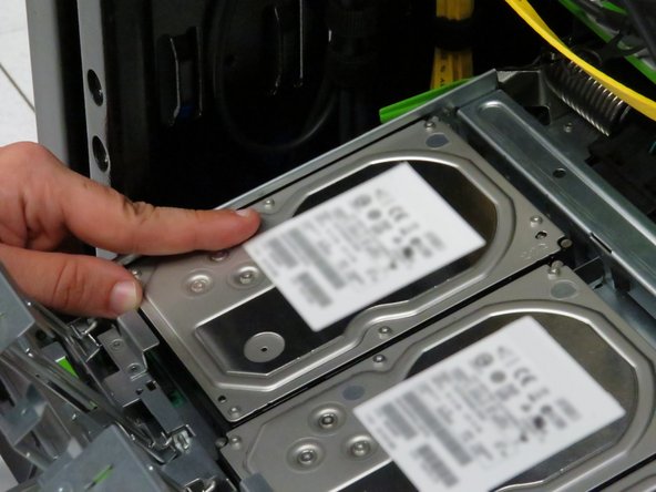
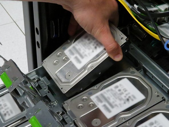
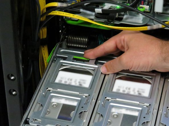
Push each hard disk drive away from the pivot point of each gate.
-
This will unseat the drives from their SATA and power connectors.
-
Remove each hard disk drive.
-
-
-
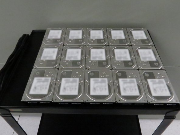
Place the hard disk drives on a work bench or cart.
-
It may be beneficial to rest the hard disk drives on an static-free mat to minimize risk of damaging the drives.
-
Because the drives will be reinstalled in the tray, it is beneficial to place them in a logical order to hasten their reinstall.
-
-
-
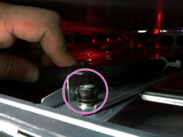
Press down two storage tray locking tabs.
-
The storage tray locking tabs are located towards the left-rear and right-rear of the tray.
-
Pull the tray away from the Open Rack.
-
If depressing the tray locking tabs do not release the tray, push the tray into the chassis about 10cm. Extend the tray again until its about 5cm from its full extension. Press the locking tabs downwards and pull the tray.
-
-
-
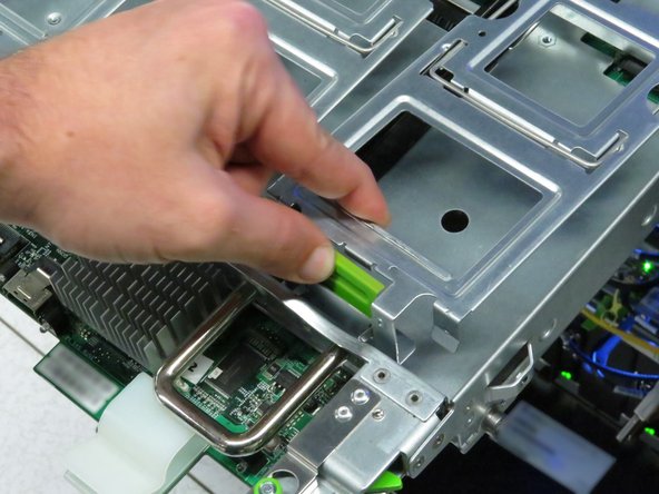
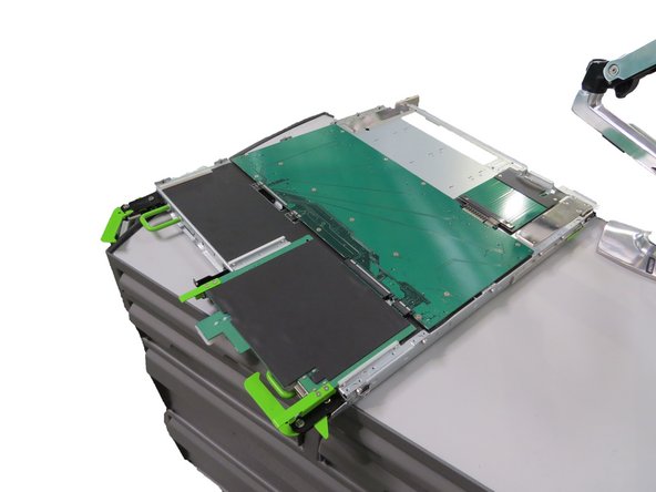
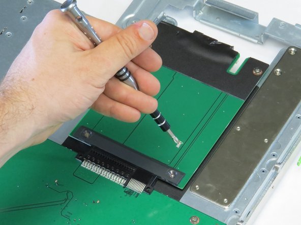
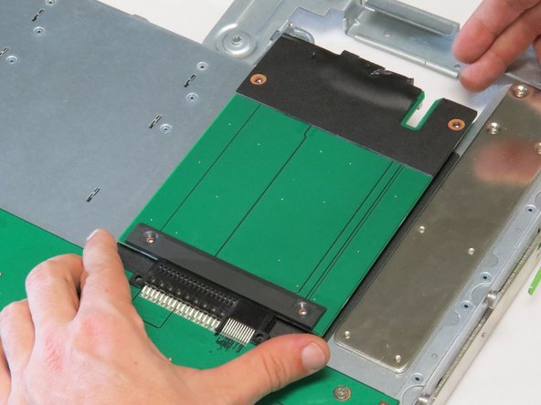
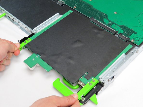
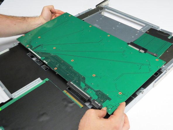
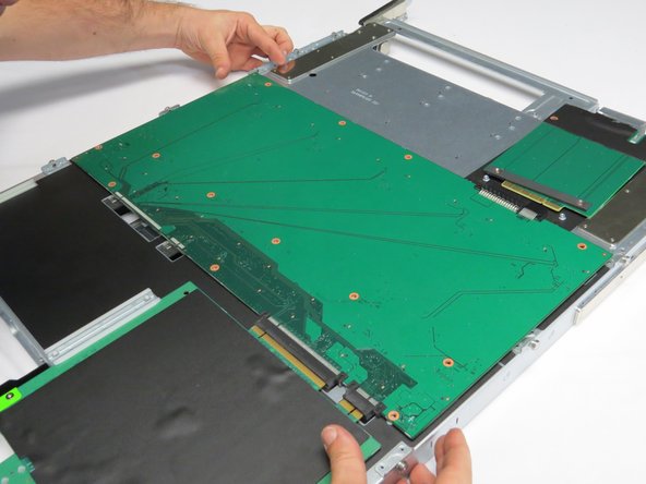
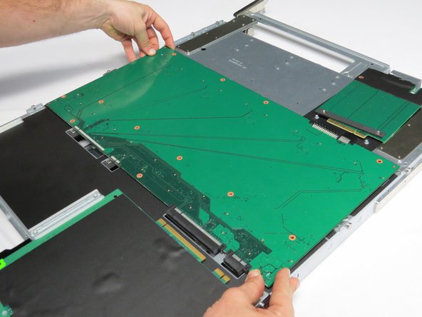
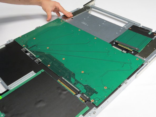
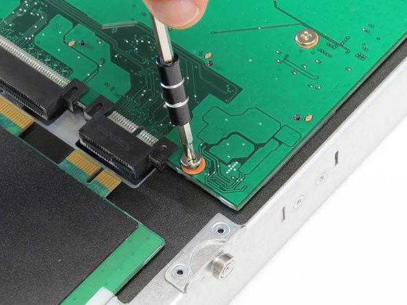
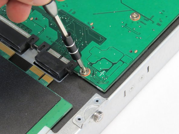
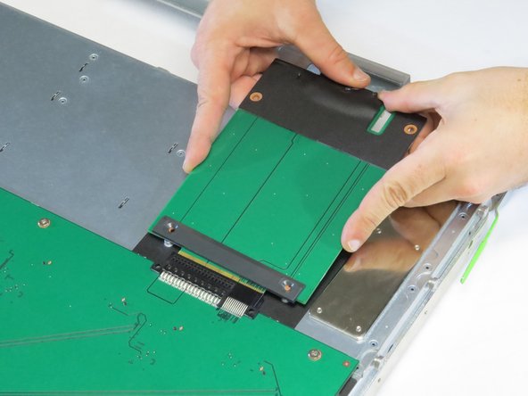
Engage the drive plane board, as shown.
-
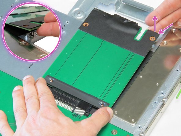
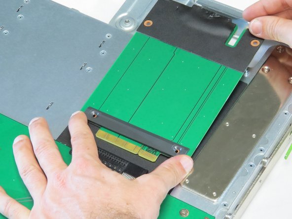
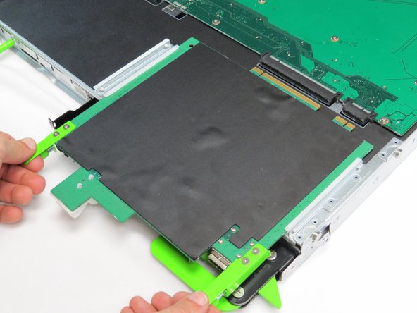
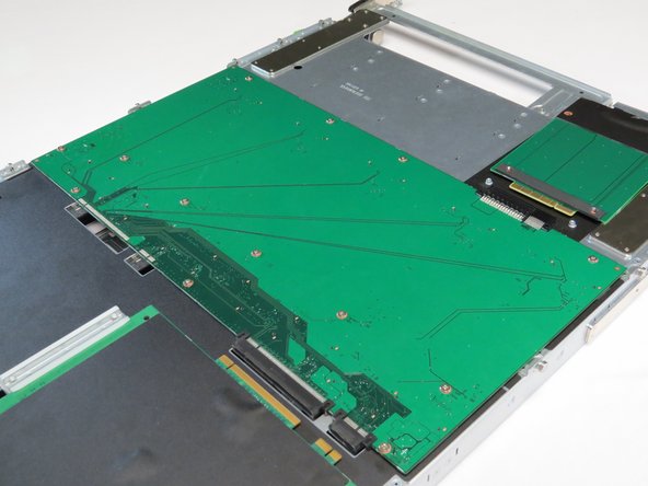
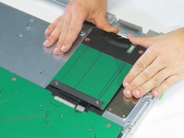
Remove the drive plane board from the storage chassis.
-
-
-
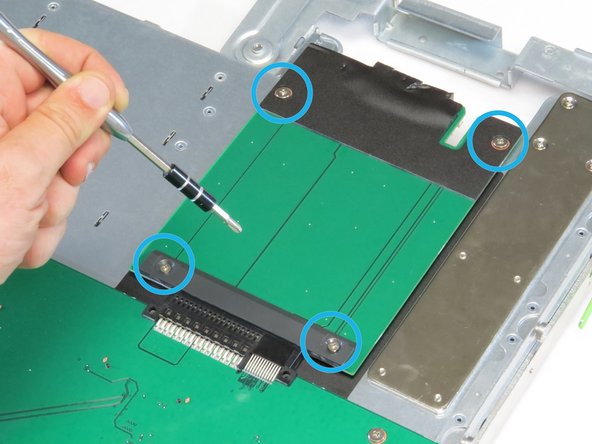
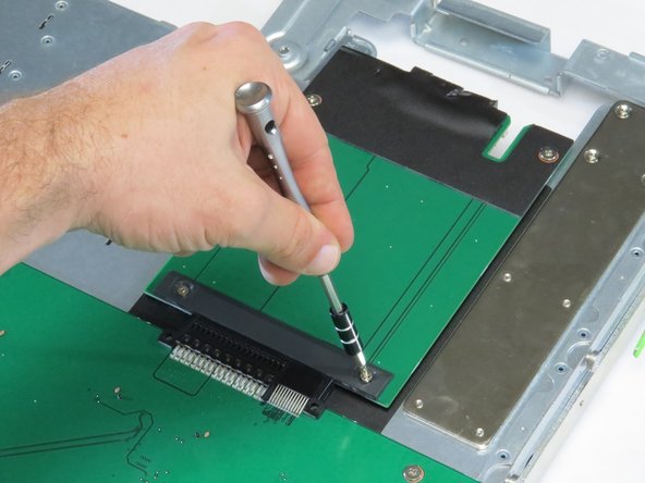
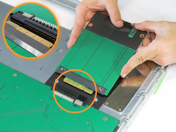
Align the new power transition board with its connector.
-
Push the board into its connector.
-


This work is licensed under a Creative Commons Attribution 4.0 International License.
This work is licensed under a Creative Commons Attribution 4.0 International License.
