Introduction

Overview

This guide demonstrates how to replace the fan control board in an Open Vault system. == Acronyms and Terms ==

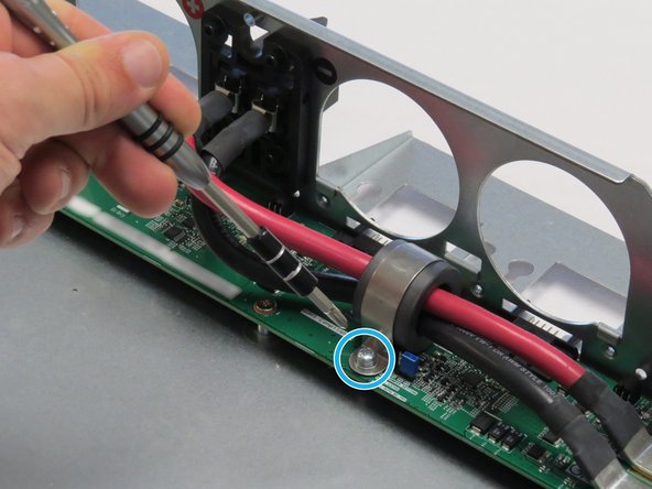
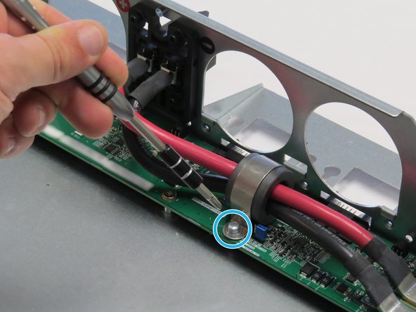
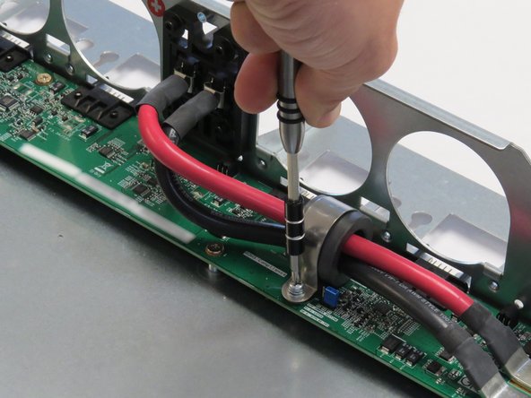
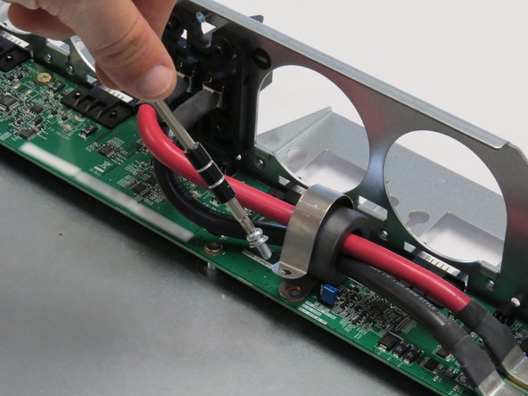
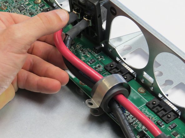
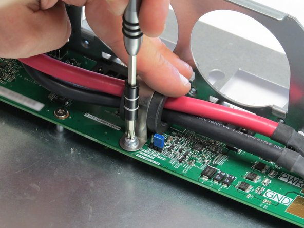
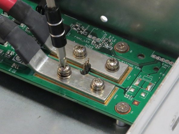
  1. Unscrew one Phillips #2 screw securing the bus lead management clip to the fan controller board. Unscrew one Phillips #2 screw securing the bus lead management clip to the fan controller board. Unscrew one Phillips #2 screw securing the bus lead management clip to the fan controller board.
    • Unscrew one Phillips #2 screw securing the bus lead management clip to the fan controller board.

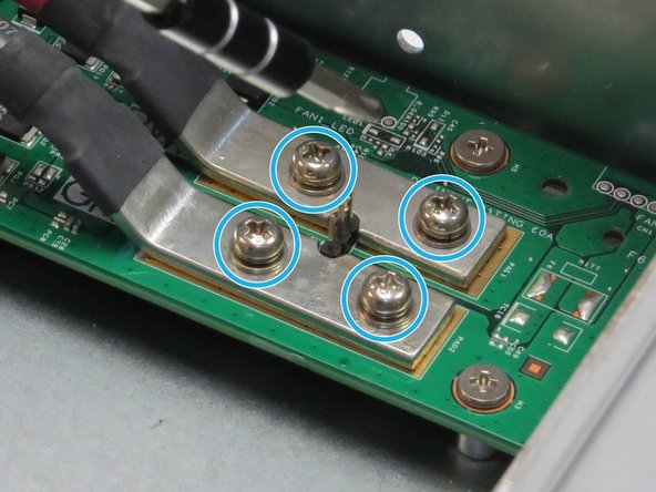
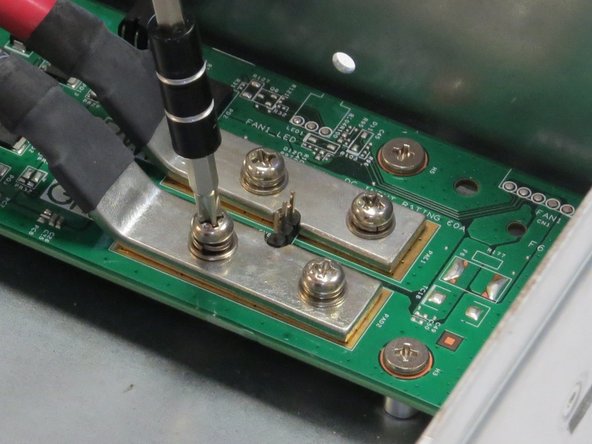
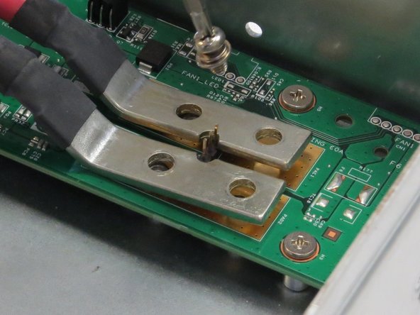
  2. Unscrew four Phillips #2 screws that secure the bus bar leads to the fan controller board. Unscrew four Phillips #2 screws that secure the bus bar leads to the fan controller board. Unscrew four Phillips #2 screws that secure the bus bar leads to the fan controller board.
    • Unscrew four Phillips #2 screws that secure the bus bar leads to the fan controller board.

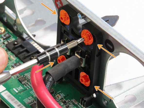
  3. Unscrew four Torx T10 screws.
    • Unscrew four Torx T10 screws.

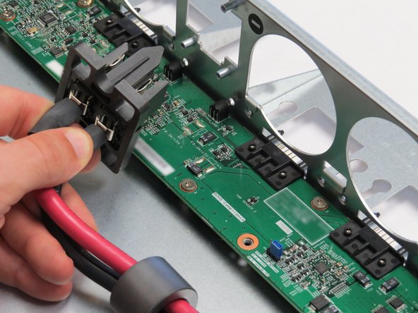
  4. Remove the bus bar clip from the Open Vault chassis. Remove the bus bar clip from the Open Vault chassis.
    • Remove the bus bar clip from the Open Vault chassis.

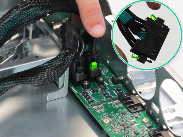
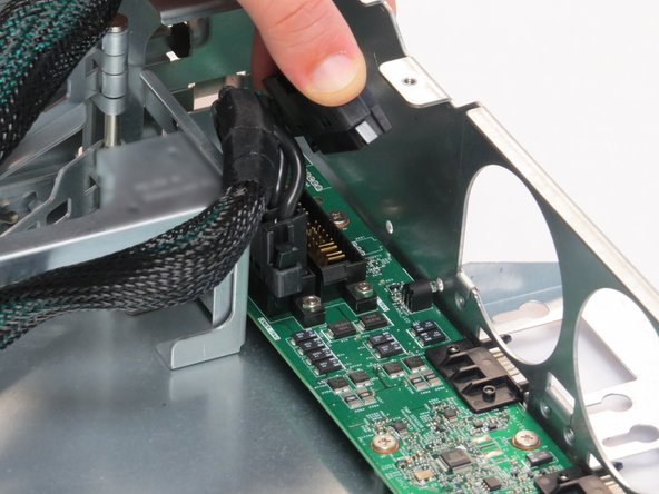
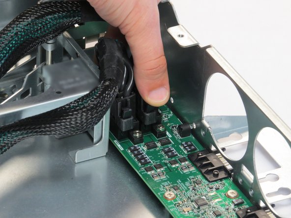
  5. Pinch the two retention tabs on the Powerblade cable, as shown. Disconnect the Powerblade cable. Disconnect the Powerblade cable.
    • Pinch the two retention tabs on the Powerblade cable, as shown.

    • Disconnect the Powerblade cable.

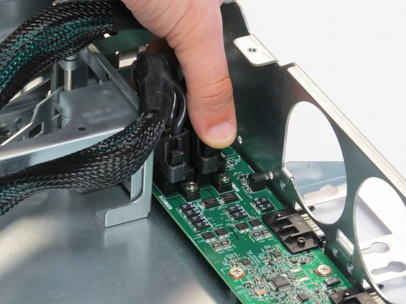
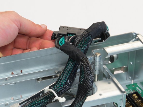
  6. Disconnect the second Powerblade cable.
    • Disconnect the second Powerblade cable.

    • Place both ends of the Powerblade cable on the side of the chassis to maximize the maintenance area.

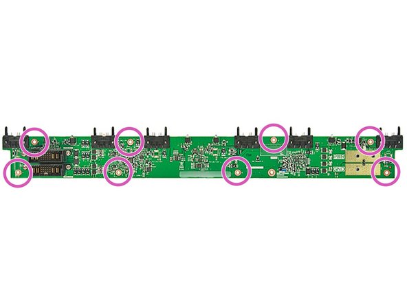
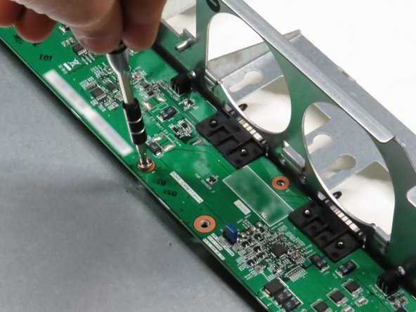
  7. Unscrew (8) Phillips #2 screws. Unscrew (8) Phillips #2 screws.
    • Unscrew (8) Phillips #2 screws.

  8. Pull the fan control board horizontally towards the front of the chassis about 2cm. Pivot the fan control board, as shown.
    • Pull the fan control board horizontally towards the front of the chassis about 2cm.

    • Pivot the fan control board, as shown.

    • Lift the fan control board away from the chassis.

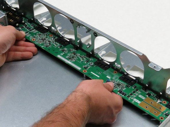
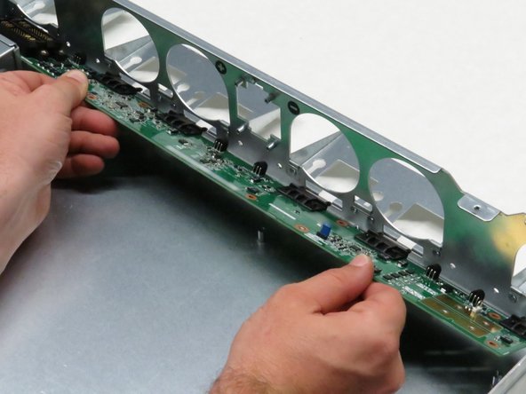
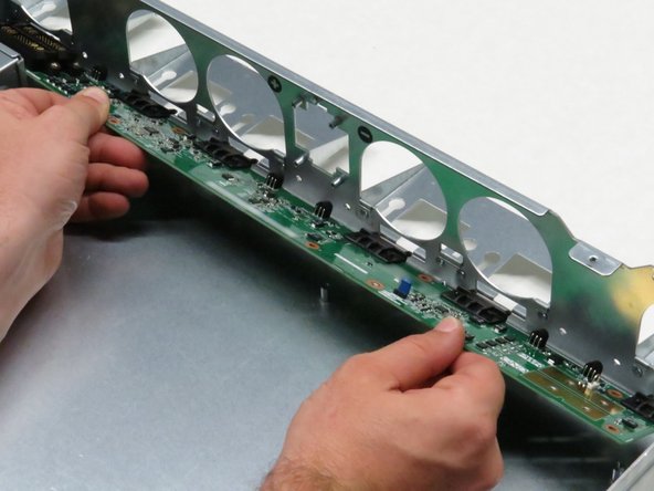
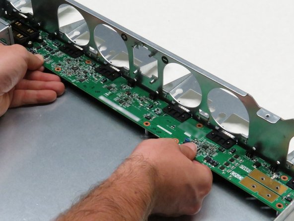
  9. Align the chassis fan socket headers into the six chassis cutouts. Place the new fan control board on the Open Vault chassis standoffs. Push the board to the rear.
    • Align the chassis fan socket headers into the six chassis cutouts.

    • Place the new fan control board on the Open Vault chassis standoffs. Push the board to the rear.

    • Align the chassis standoffs with the fan control board screw holes.

  10. Install the eight Phillips #2 screws.
    • Install the eight Phillips #2 screws.

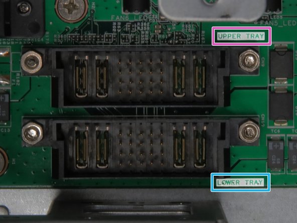
  11. Connect the two Powerblade cables. Be mindful of the orientation of the two Powerblade cables. The top-most tray Powerblade cable connects to the socket labeled UPPER TRAY. The lower tray Powerblade cable connects to the socket labeled LOWER TRAY. Be mindful of the orientation of the two Powerblade cables. The top-most tray Powerblade cable connects to the socket labeled UPPER TRAY. The lower tray Powerblade cable connects to the socket labeled LOWER TRAY.
    • Connect the two Powerblade cables.

    • Be mindful of the orientation of the two Powerblade cables. The top-most tray Powerblade cable connects to the socket labeled UPPER TRAY. The lower tray Powerblade cable connects to the socket labeled LOWER TRAY.

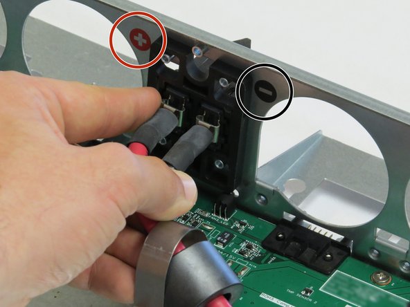
  12. Insert a new bar clip into the chassis.
    • Insert a new bar clip into the chassis.

    • It is important to ensure that positive and negative lead polarity is oriented as indicated by the markings on the chassis, as annotated. Power polarity is indicated as follows:

    • PWR: (+)

    • GND: (-)

  13. Screw in the Phillips #2 screw to secure the bus lead management clip to the fan controller board. Screw in the Phillips #2 screw to secure the bus lead management clip to the fan controller board.
    • Screw in the Phillips #2 screw to secure the bus lead management clip to the fan controller board.

  14. Screw in four Phillips #2 screws to secure the bus leads to the fan controller board.
    • Screw in four Phillips #2 screws to secure the bus leads to the fan controller board.

    • It is important to ensure that positive and negative lead polarity is oriented as indicated by the markings on the chassis. Power polarity is indicated as follows:

    • PWR: (+)

    • GND: (-)

Conclusion

Dozuki System

Member since: 9/24/09

1 Reputation

142 Guides authored

0 Comments

Add Comment


View Statistics:

Past 24 Hours: 0

Past 7 Days: 0

Past 30 Days: 0

All Time: 0