
-
-
The server can be powered off remotely or on the hardware itself.
-
Remote Power Down: Login to the server to power it off.
-
shutdown -h now;exit -
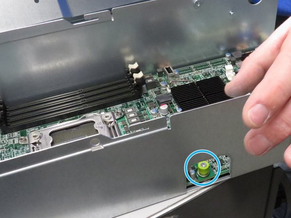
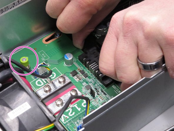
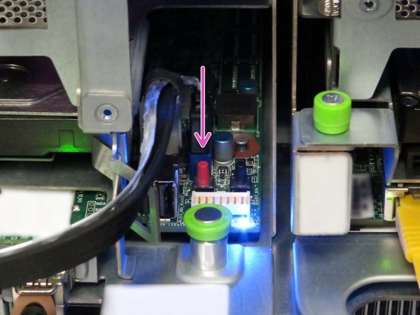
Hardware Power Down: Press and hold the power switch for at least three seconds, as annotated.
-
-
-
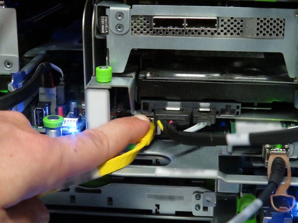
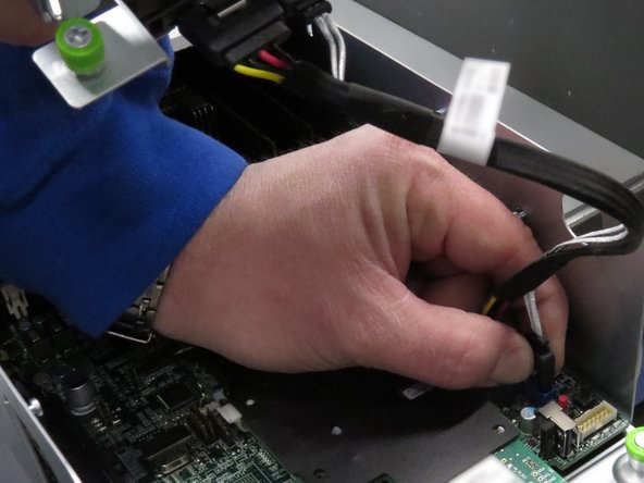
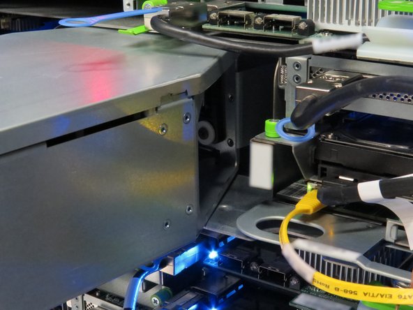
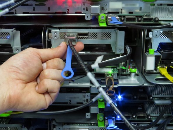
Disconnect the Mini-SAS cable by pulling on the pull-tab, as shown.
-
-
-
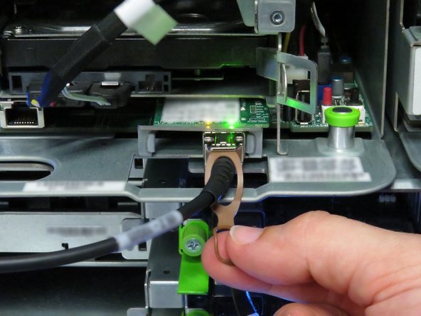
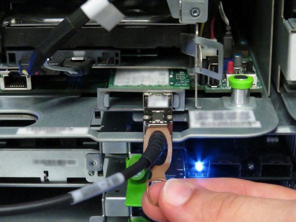
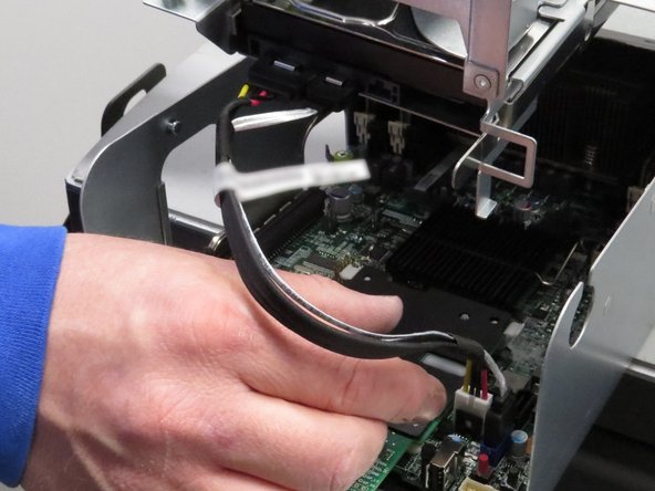
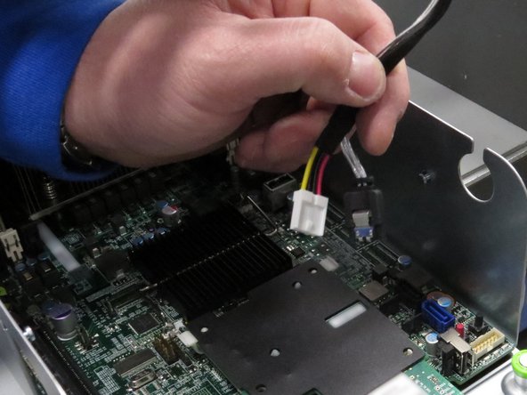
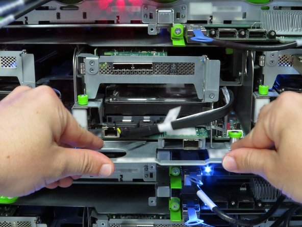
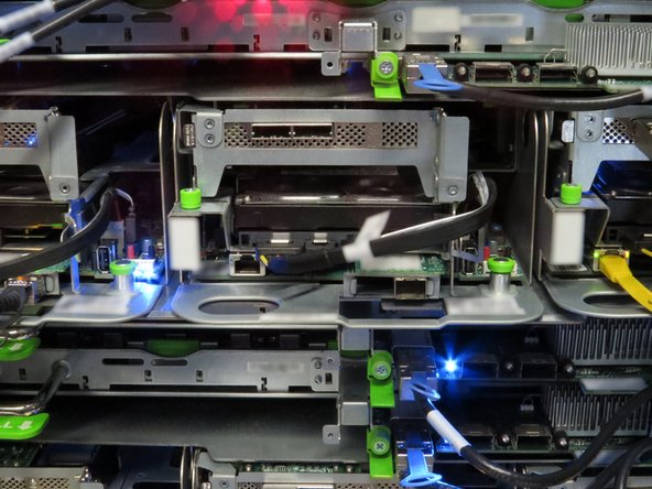
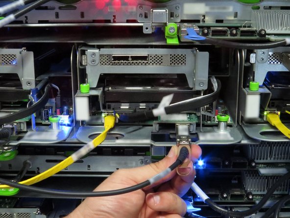
Disconnect the Ethernet cable from the server.
-
Press the tab on the end of the cable to release it.
-
-
-
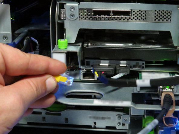
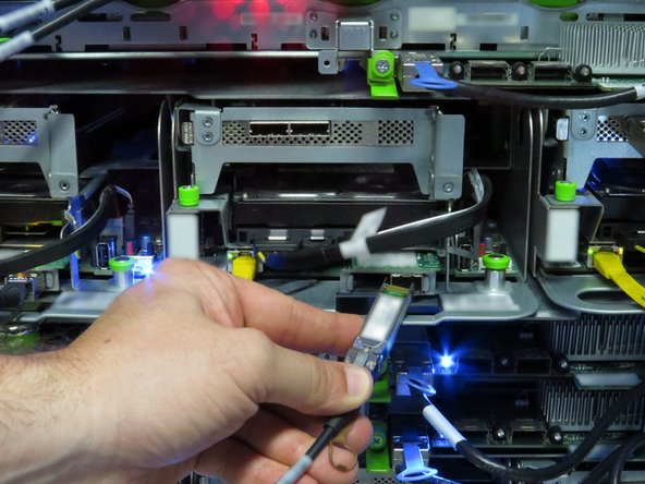
Disconnect the 10G SFP+ cable by pulling on the pull-tab, as shown.
-
-
-
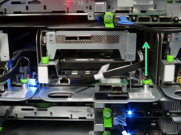
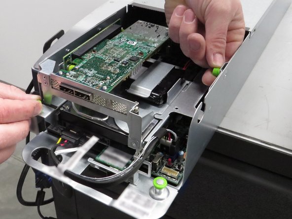
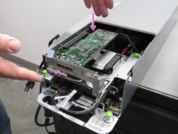
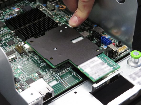
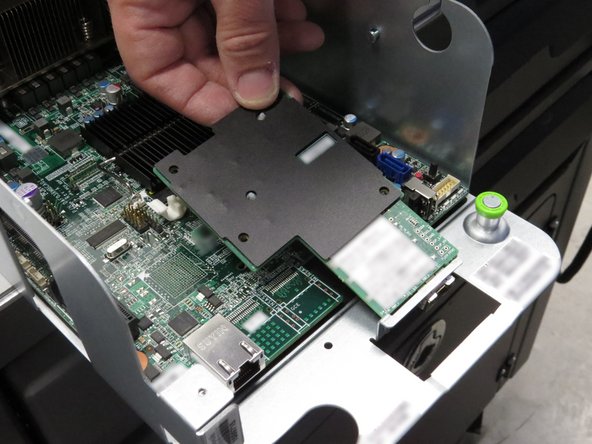
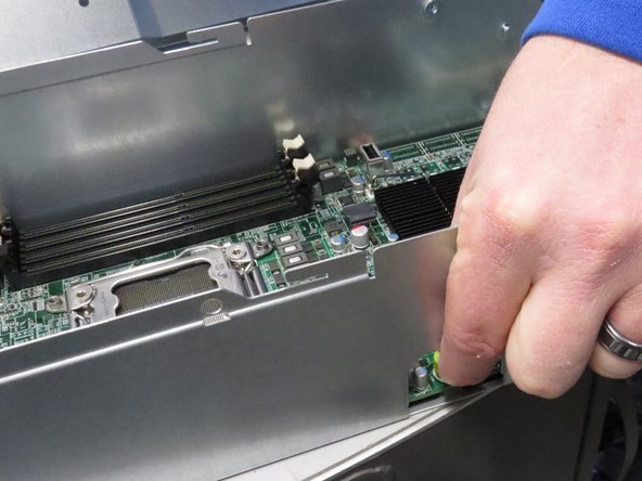
Pull the retention plunger upwards.
-
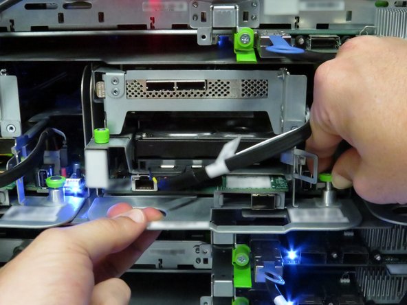
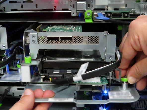
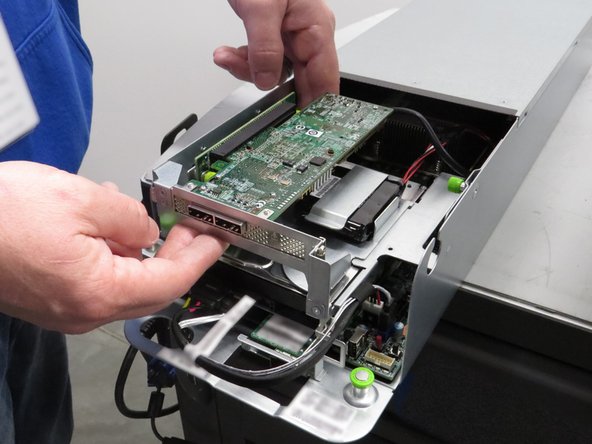
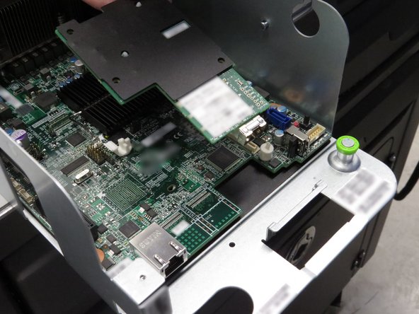
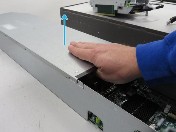
Grasp the server as shown.
-
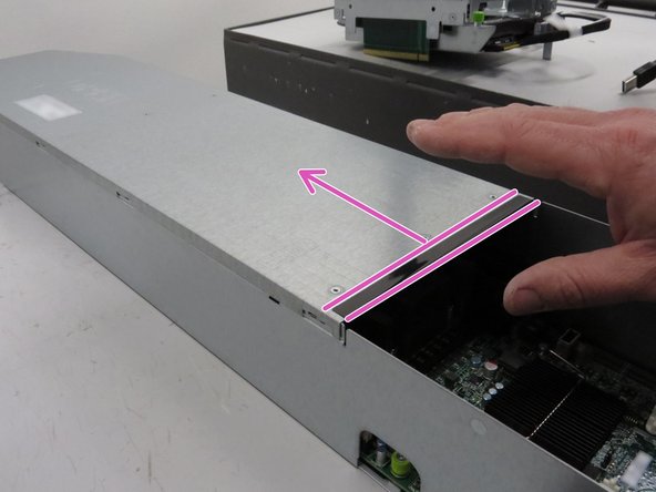
Remove the server from the rack.
-
-
-
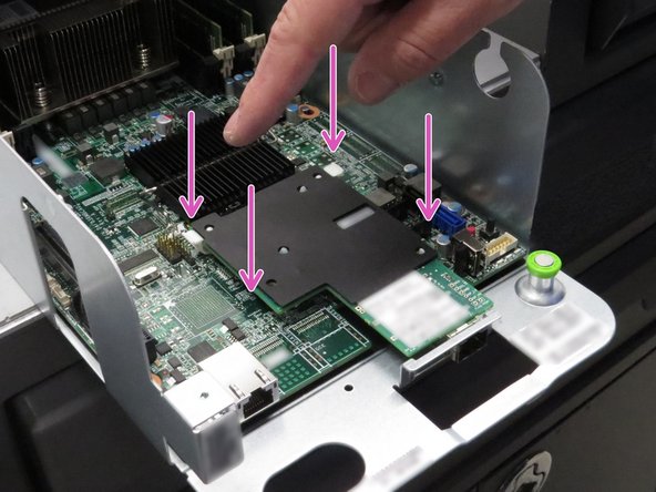
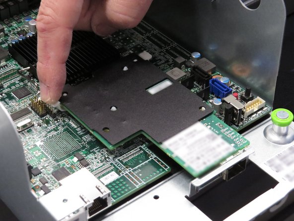
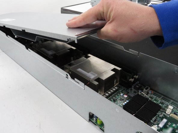
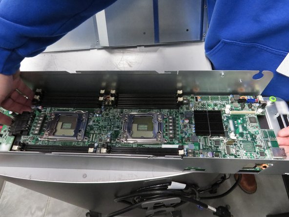
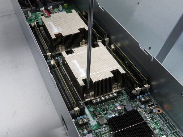
Install the new motherboard into the server chassis.
-
Motherboard installation is opposite of the removal process.
-
-
-
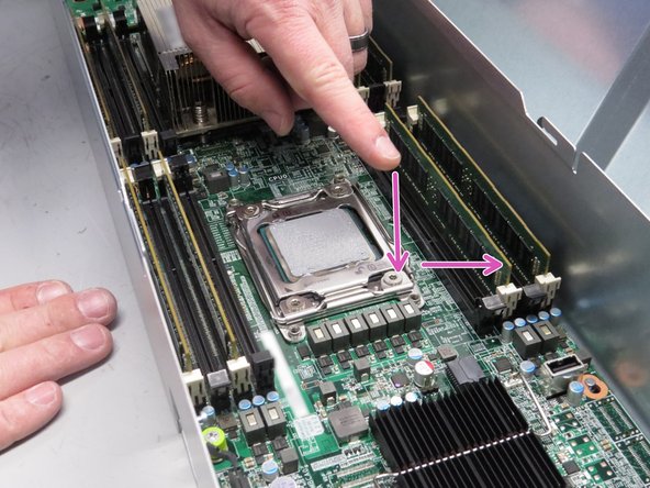
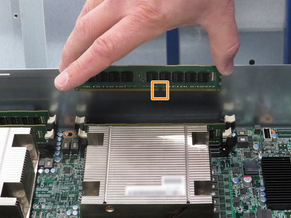
Install the DIMMs into their respective slots.
-
When installing DIMMs, be aware of the orientation of the slot key. If the DIMM is not seating correctly, it is possible the DIMM needs to be rotated.
-
-
-
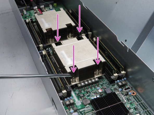
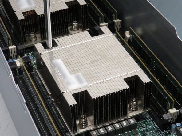
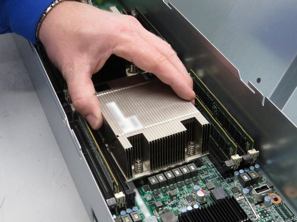
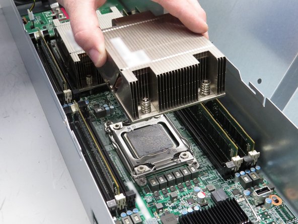
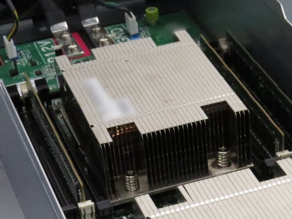
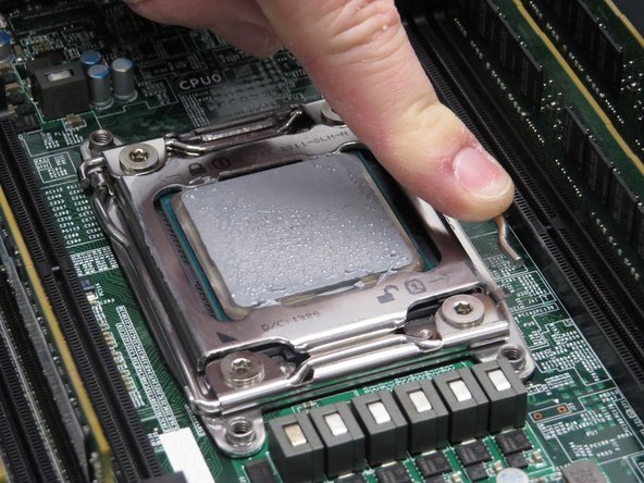
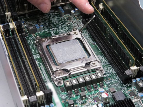
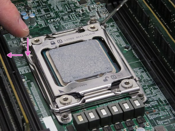
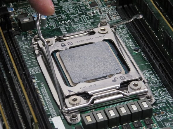
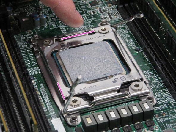
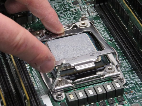
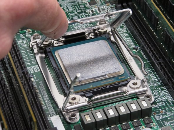
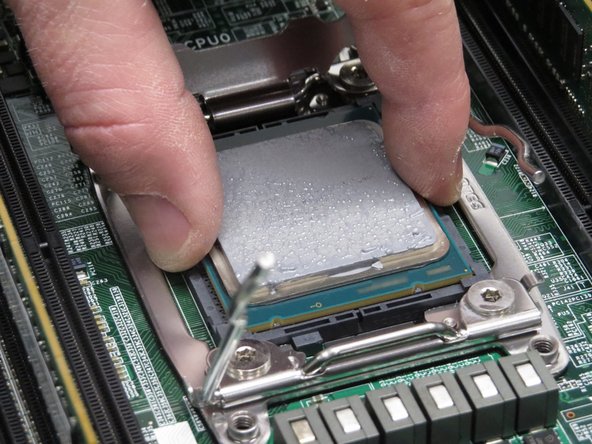
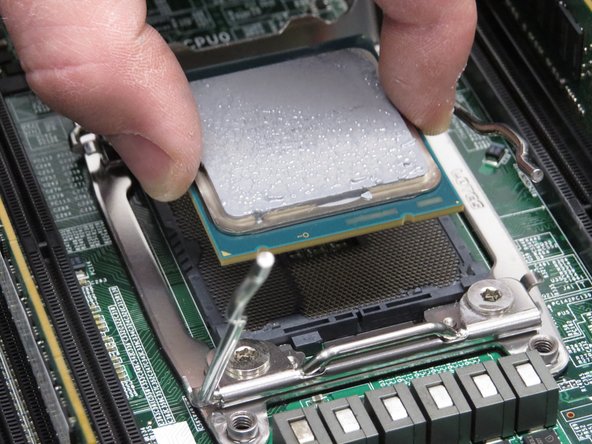
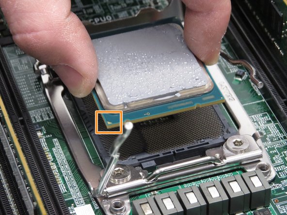
Install the CPUs that were previously removed.
-
When installing CPU, be aware of the orientation of the CPU socket. The arrows on the CPU and the CPU socket must align. If the CPU is not seated correctly, it is possible to damage the CPU socket pins.
-
-
-
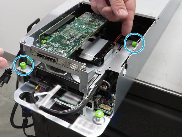
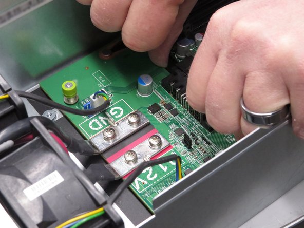
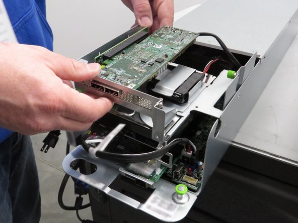
Install the riser cage.
-
Riser cage installation is opposite of the removal process.
-
-
-
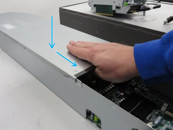
Place the server in the slot where it was previously removed.
-
Push the server into the slot.
-
Do not use the chassis handle as it could pinch your hand.
-
-
-
Connect the Ethernet cable to the RJ45 port on the server motherboard.
-


This work is licensed under a Creative Commons Attribution 4.0 International License.
This work is licensed under a Creative Commons Attribution 4.0 International License.

One Comment
such a great explanation with images.
I was soo worried about how to replace the motherboard? but now I am understood. thanks for sharing with us.