
Difficulty
Moderate
Steps
16
Time Required
- Midplane Board Replacement 16 steps

Unnecessary Steps
This guide contains steps that are not necessary.
Tools
Parts
No parts specified.
-
-
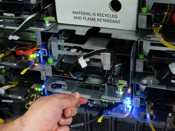
Disconnect the 10G network interface cable.
-
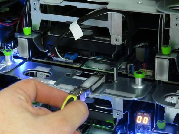
Pull the 10G network interface cable pull-tab.
-
-
-
Pull the green retention plunger upwards.
-
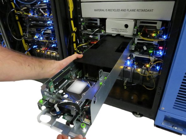
Pull the server away from the rack, as shown.
-
Pull the server until about (2) inches of the black lid is exposed.
-
-
-
Move the server on the crash cart for transportation or out of rack repairs.
-
-
-
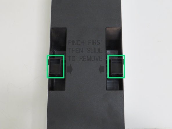
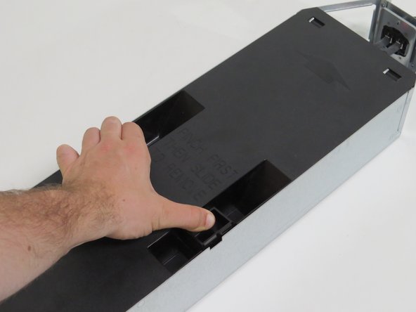
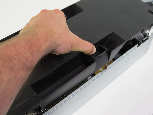
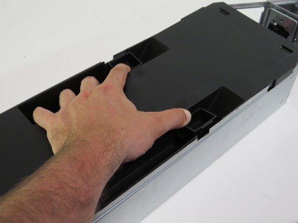
Squeeze (2) lid retention handles towards the center of the node.
-
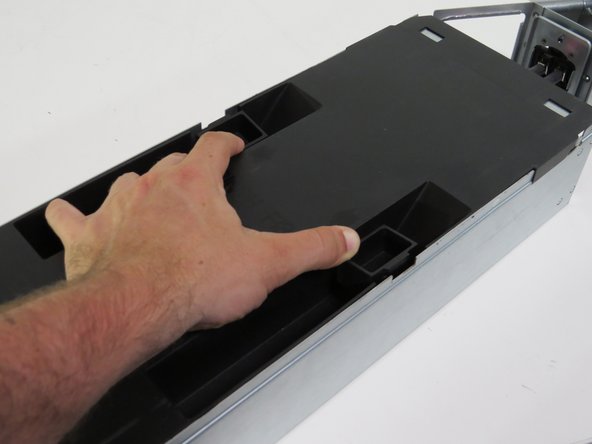
Slide the lid towards the rear of the server node.
-
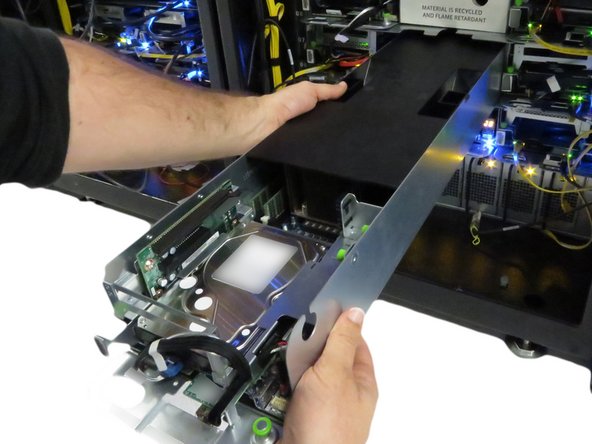
Lift and remove the lid.
-
-
-
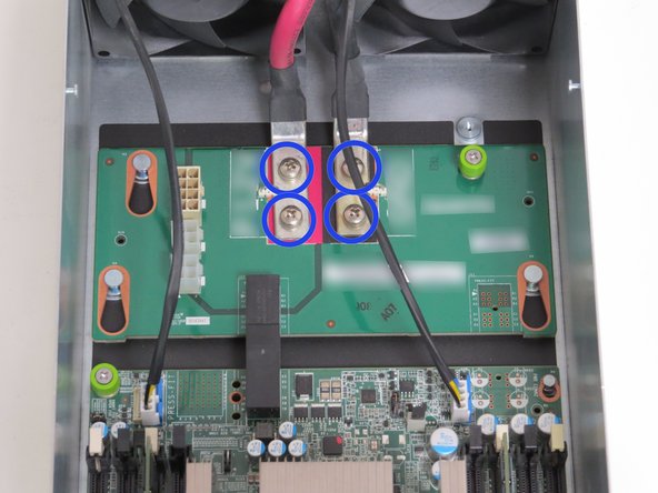
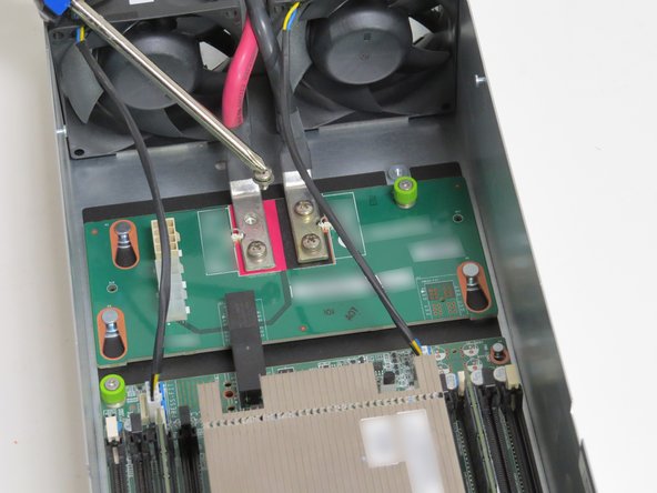
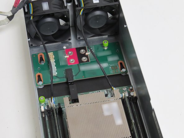
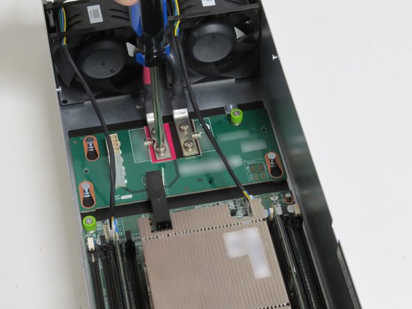
Unscrew (4) Philips # 2 screws.
-
These screws secure the bus bar server power leads.
-
Place the screws in a secure spot. These screws will be reused.
-
-
-
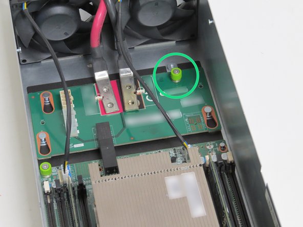
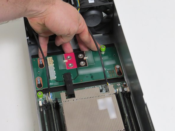
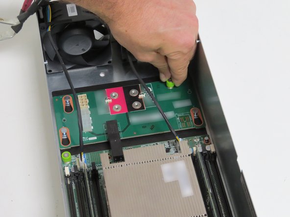
Loosen (1) thumbscrew.
-
-
-
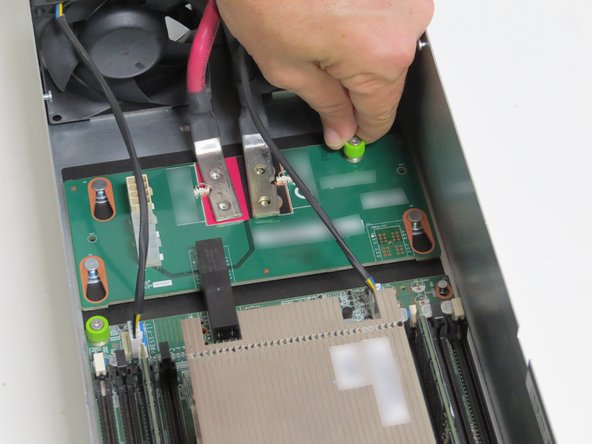
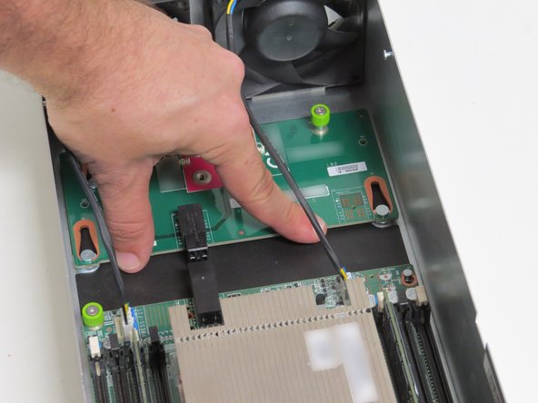
Slide the board to the rear of the server until resistance is felt.
-
-
-
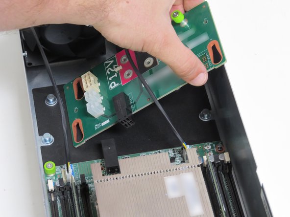
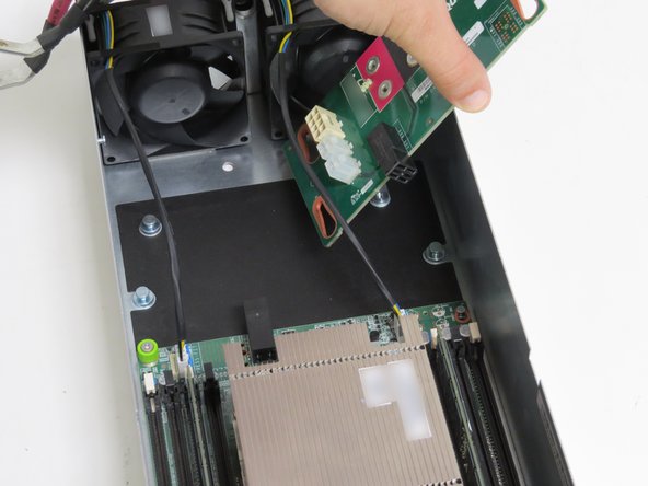
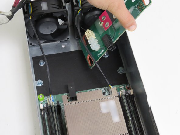
Lift the board towards the right and up from the server.
-
Take care not the power cable connected to system fan 1.
-
-
-
Insert the midplane board into the server.
-
This process is exactly the opposite of how it was removed.
-
-
-
Slide the board towards the front of the server, until resistance is felt.
-
-
-
Tighten (1) thumbscrew.
-
-
-
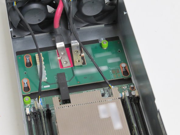
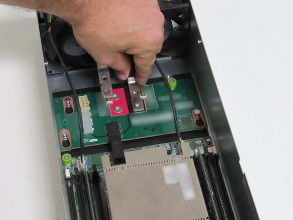
Seat the bus bar leads on the midplane board.
-
Make certain the red lead sets on the red midplane board silkscreen, and the black lead sets on the black midplane board silkscreen.
-
Screw in (4) Phillips # 2 screws.
-
-
-
Install the lid on the server, as shown.
-
-
-
Slide the server back into the rack.
-
Continue pushing the server until the server chassis pin secures the server.
-
A distinctive 'click' will be felt when the pin secures the server in the rack.
-
-
-
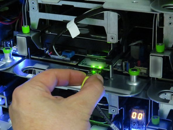
Connect the 10G network interface cable.
-
-
-
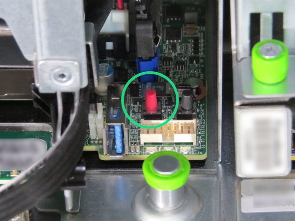
Press the power button.
-



This work is licensed under a Creative Commons Attribution 4.0 International License.
This work is licensed under a Creative Commons Attribution 4.0 International License.
