
Difficulty
Moderate
Steps
16
Time Required
- Midplane Board Replacement 16 steps

Unnecessary Steps
This guide contains steps that are not necessary.
Quiz
0
Tools
Parts
No parts specified.
-
-
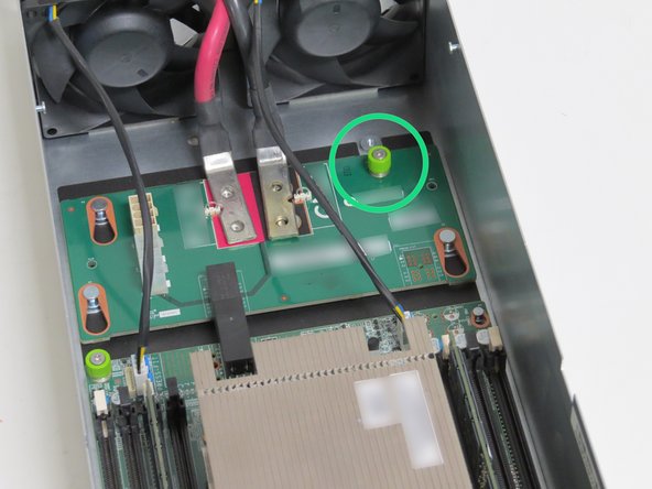
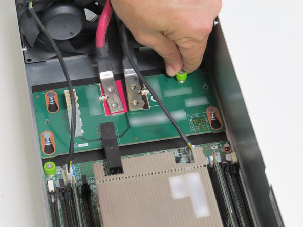
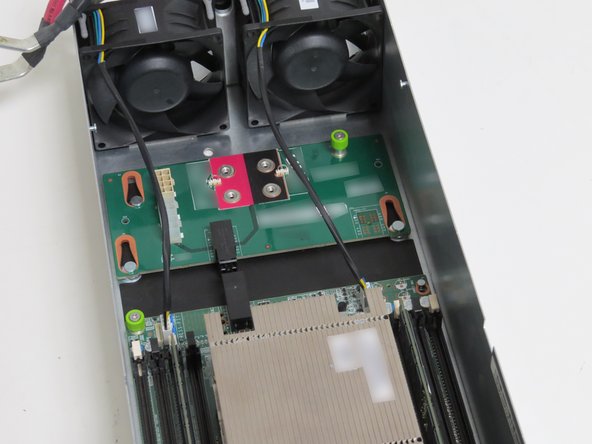
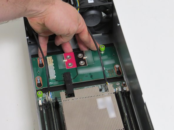
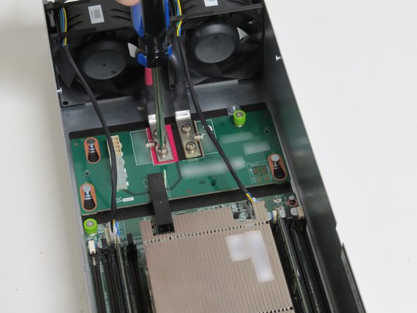
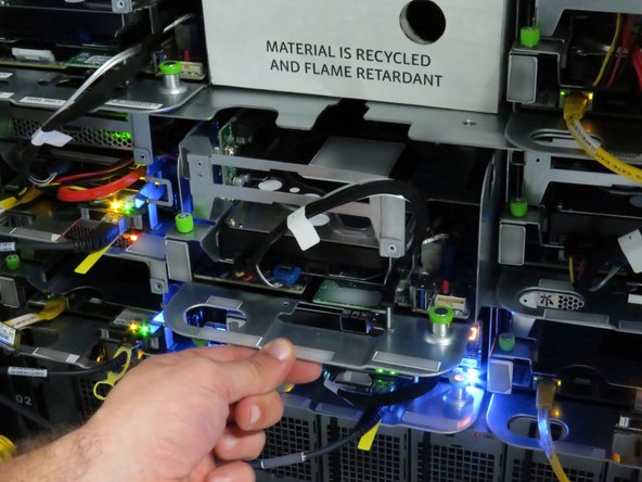
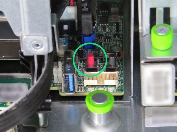
Disconnect the 10G network interface cable.
-
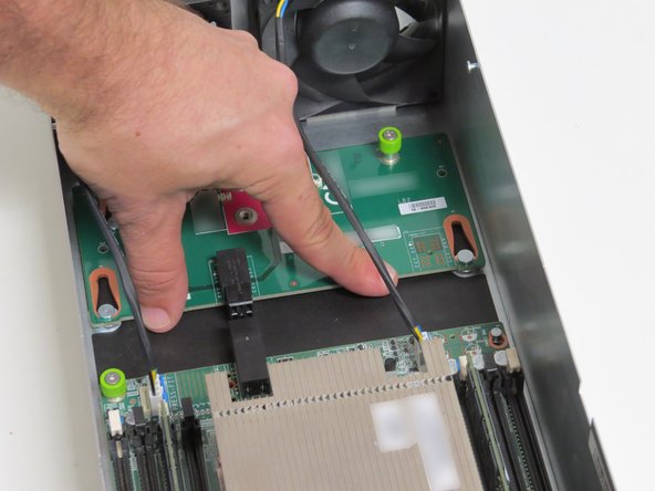
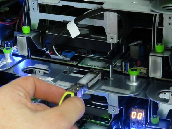
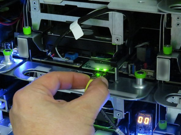
Pull the 10G network interface cable pull-tab.
-


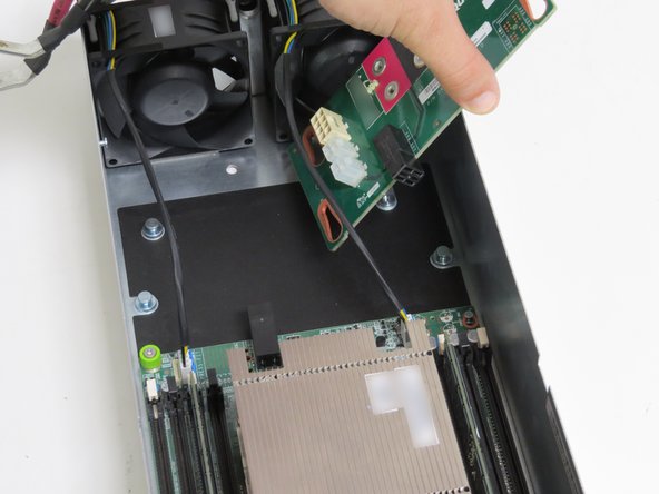

Almost done!
This work is licensed under a Creative Commons Attribution 4.0 International License.
Conclusion
This work is licensed under a Creative Commons Attribution 4.0 International License.
