
Difficulty
Moderate
Steps
40
Time Required
- Motherboard Replacement 40 steps

Unnecessary Steps
This guide contains steps that are not necessary.
Tools
Parts
No parts specified.
-
-
Perform a warm shut down on the server. Run:
-
ssh -l root <hostname> shutdown -h now
-
-
-
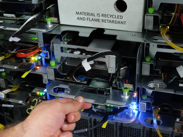
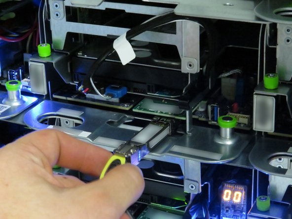
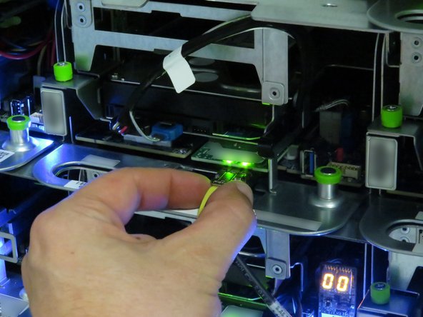
Disconnect the 10G network interface cable.
-
Pull the 10G network interface cable pull-tab.
-
-
-
Pull the green retention plunger upwards.
-
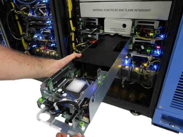
Pull the server away from the rack, as shown.
-
Pull the server until about (2) inches of the black lid is exposed.
-
-
-
Move the server on the crash cart for transportation or out of rack repairs.
-
-
-
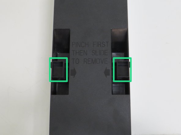
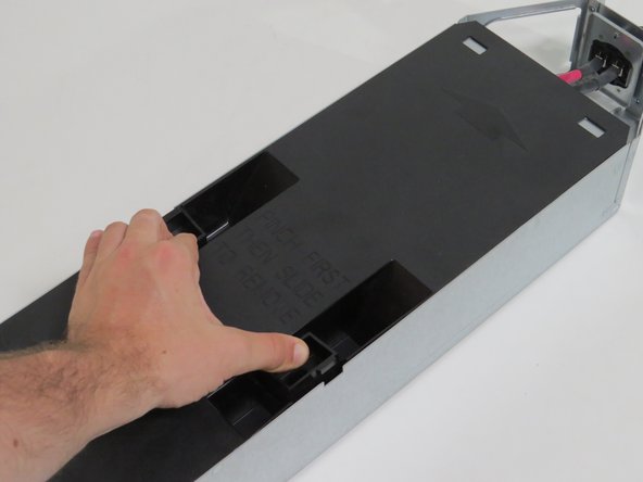
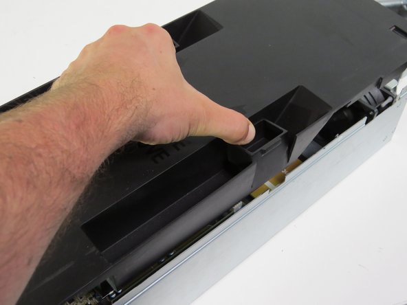
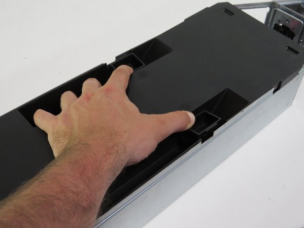
Squeeze (2) lid retention handles towards the center of the node.
-
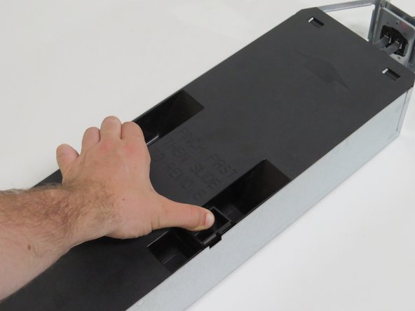
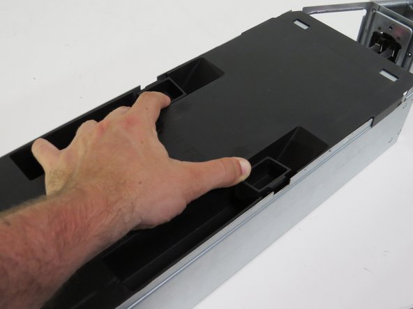
Slide the lid towards the rear of the server node.
-
Lift and remove the lid.
-
-
-
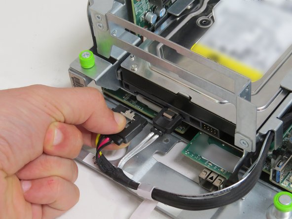
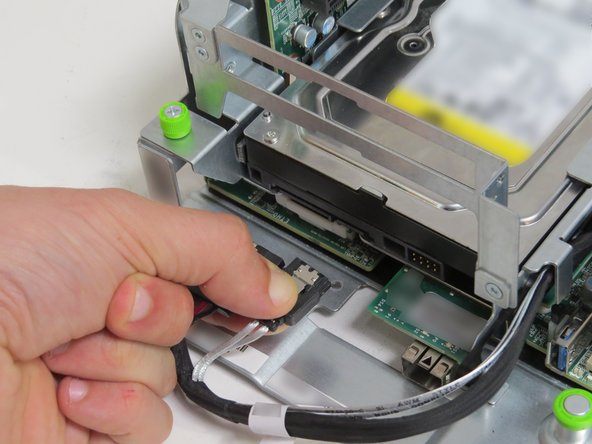
Disconnect the SATA from the hard disk drive (HDD).
-
Disconnect the power cable from the HDD.
-
-
-
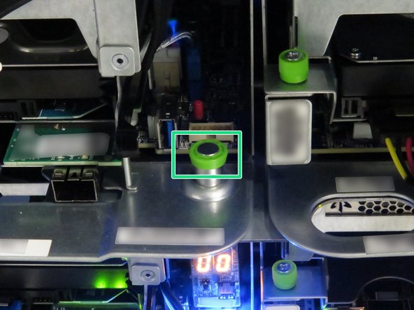
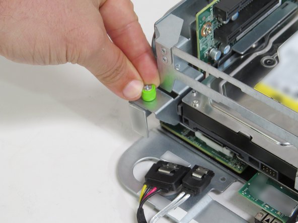
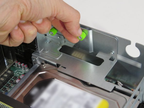
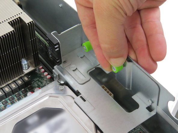
Loosen (2) thumbscrews.
-
Loosen the thumbscrew near the Facebook part number, as shown.
-
Loosen the thumbscrew on the right side of the PCI riser card assembly, as shown.
-
-
-
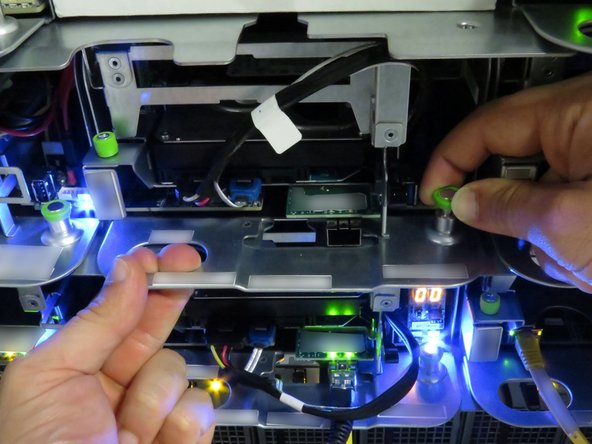
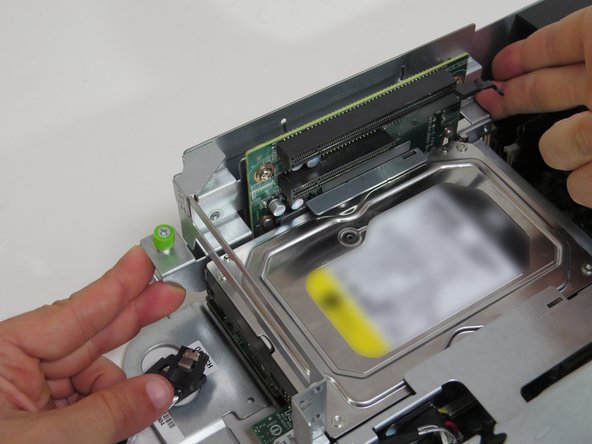
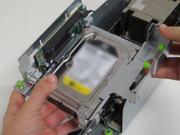
Engage the riser card assembly, as shown.
-
Push the riser card assembly upwards, until a 'click' is felt.
-
-
-
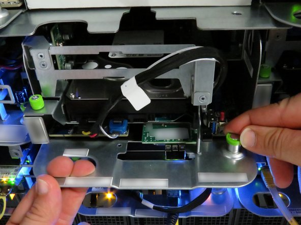
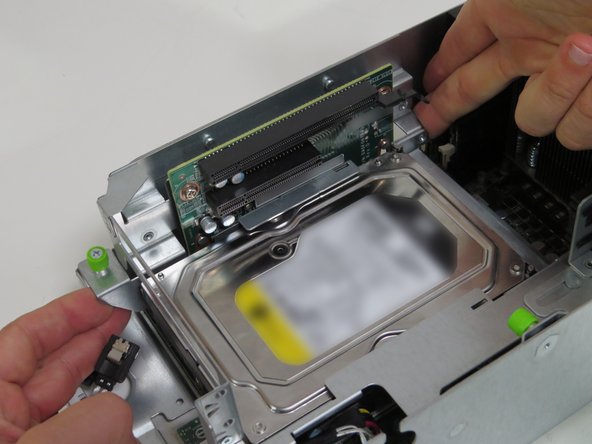
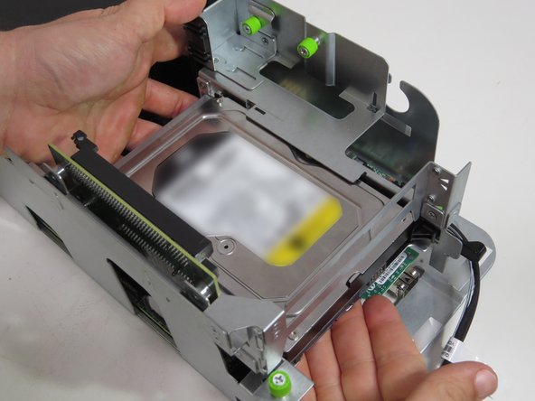
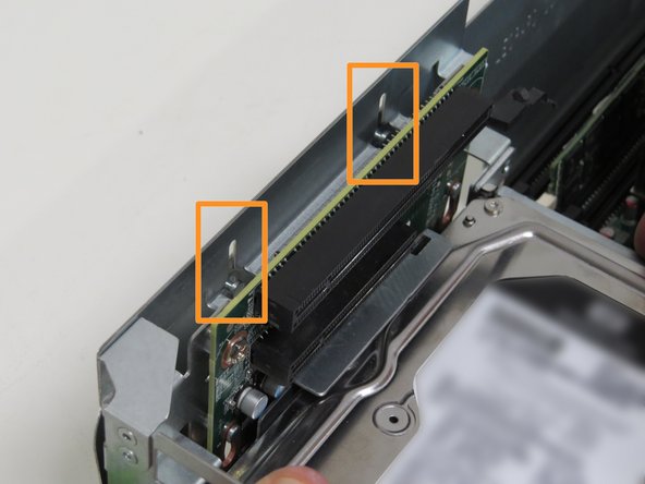
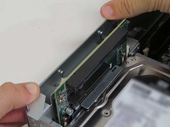
Lift the riser card assembly from the server.
-
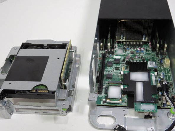
Place the riser card assembly next to the server with the riser card pins facing up, as shown.
-
-
-
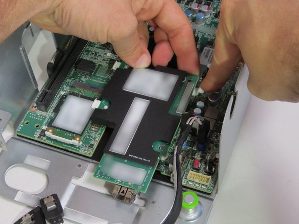
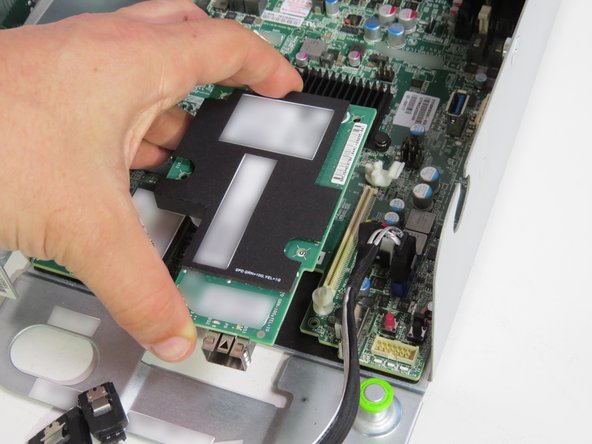
Press (3) retention clips to unseat the NIC.
-
Lift the NIC from the motherboard.
-
Place the NIC on the work bench.
-
-
-
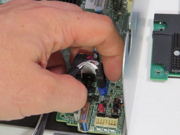
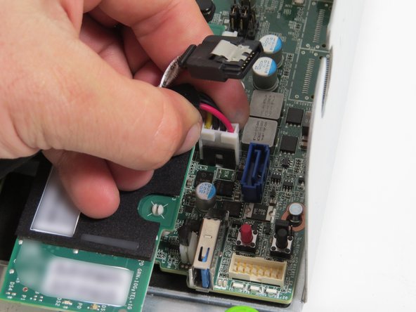
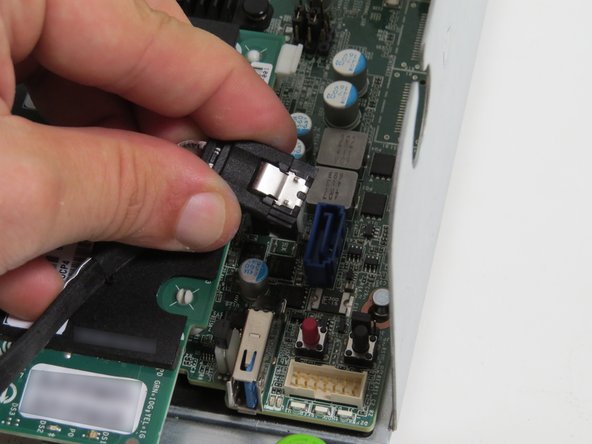
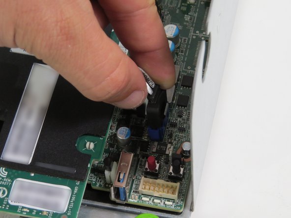
Disconnect the SATA cable from the motherboard.
-
Squeeze the cable connector to ensure the metal retention tab is depressed.
-
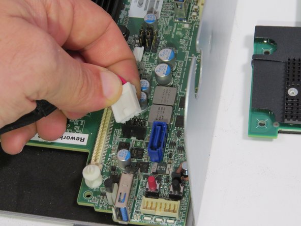
Disconnect the hard disk drive (HDD) power cable from the motherboard.
-
Place the cable on the work bench. This cable will be installed again at a later point.
-
-
-
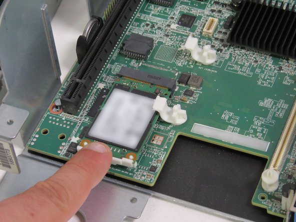
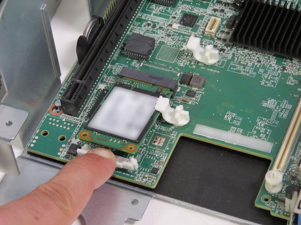
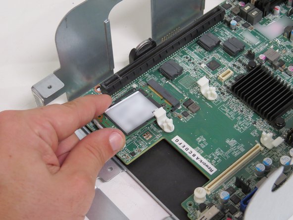
Engage the mSATA drive and drive clip, as shown.
-
Lightly pull the drive clip towards the front of the chassis with your index finger.
-
-
-
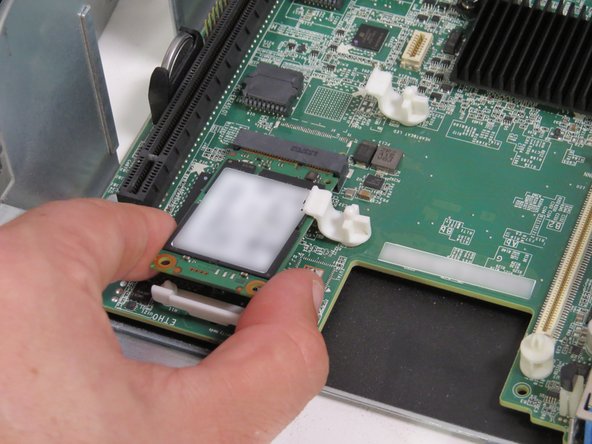
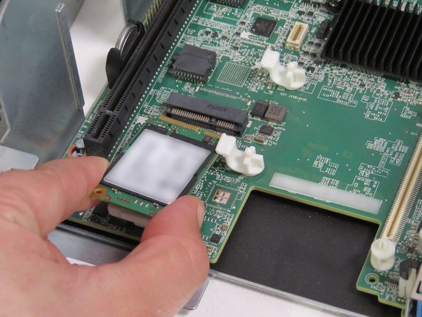
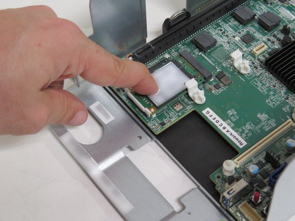
Pull the mSATA drive away from its socket.
-
Place the mSATA drive on the work bench. It will be installed at a later point.
-
-
-
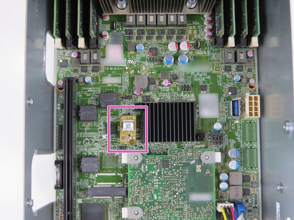
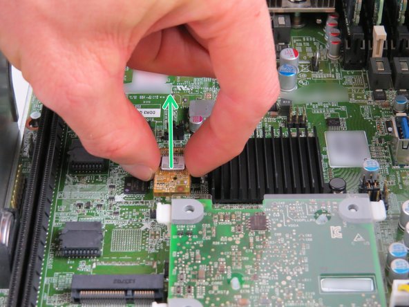
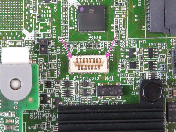
Locate the TPM Module.
-
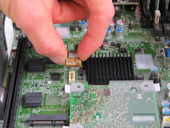
To remove, grip the module on each side, then pull upwards as shown.
-
Place the TPM Module on a work bench. This will be installed again at a later point.
-
-
-
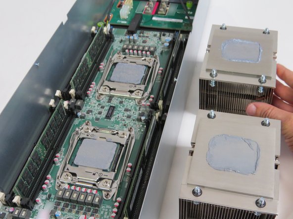
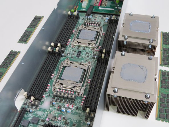
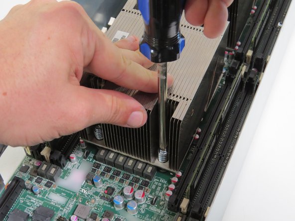
Remove (2) CPU heatsinks.
-
Place each heatsink next to their respective CPU socket.
-
Ensure the heatsink is facing with thermal compound facing up.
-
[invalid guide link].
-
-
-
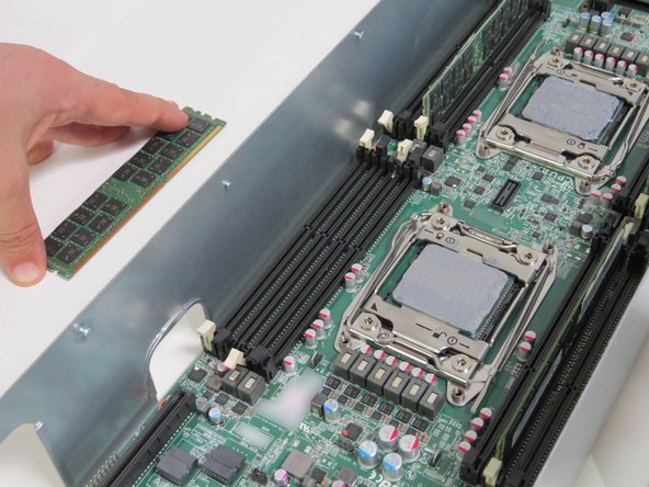
DIMM quantity is variant upon server type. Refer to the DIMM and CPU Identification guide for exact DIMM capacity.
-
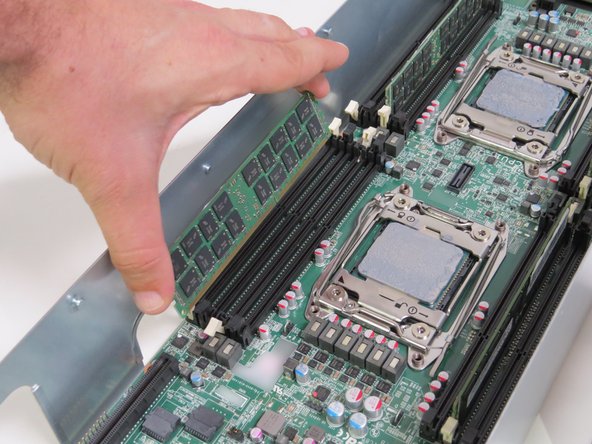
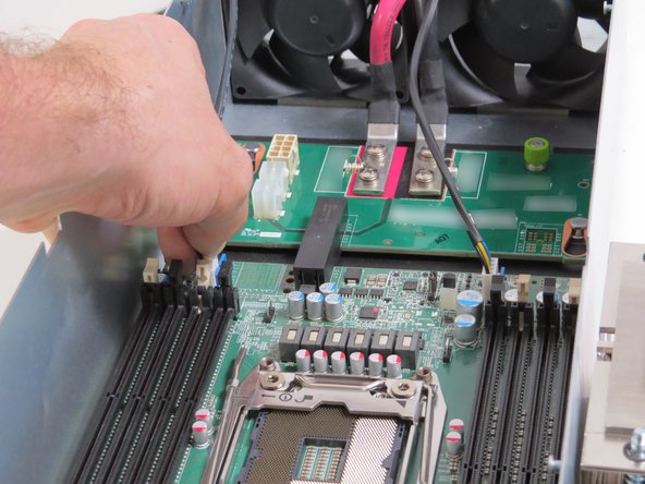
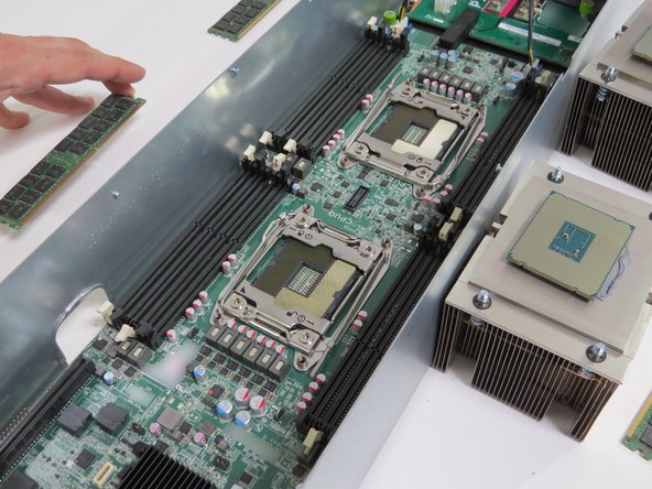
Disconnect and remove all the DIMMs.
-
Place each DIMM next to their respective socket, as shown.
-
For detailed DIMM removal instructions, [invalid guide link]
-
-
-
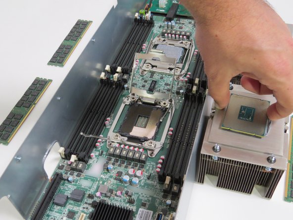
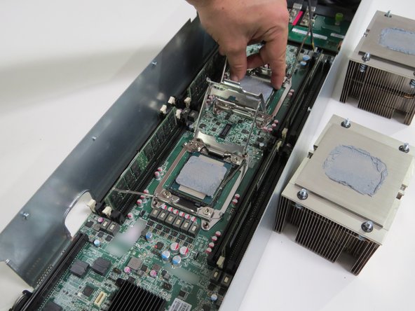
Remove (2) CPUs.
-
Place the CPUs on top of their respective heatsinks
-
[invalid guide link]
-
-
-
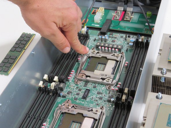
Close (2) CPU retention brackets.
-
-
-
Disconnect (2) fan power cables.
-
-
-
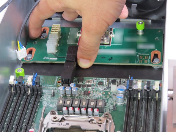
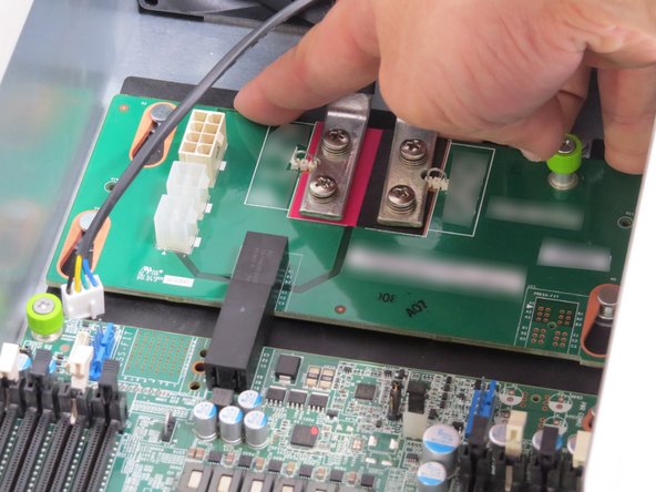
Loosen (1) midplane board thumbscrew.
-
Slide the midplane board towards the fans, until resistance is felt.
-
Tighten (1) midplane board thumbscrew.
-
This will keep the midplane board from interfering with the motherboard.
-
-
-
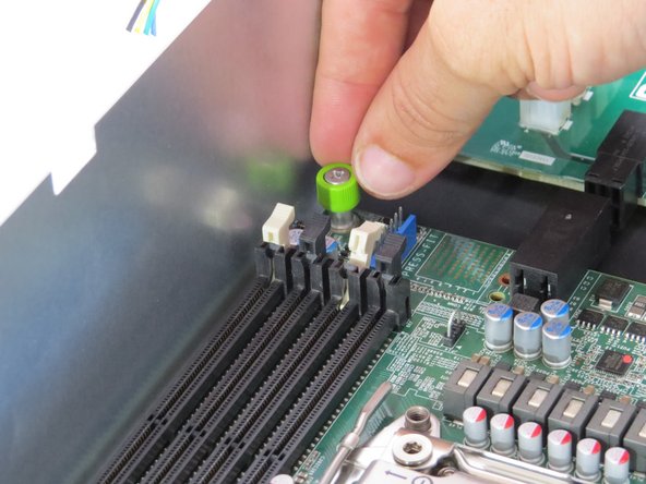
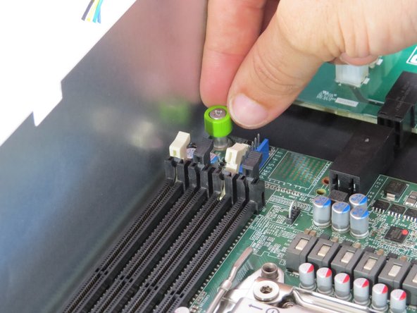
Loosen (1) motherboard thumbscrew.
-
This thumbscrew is located on the top left of the motherboard.
-
-
-
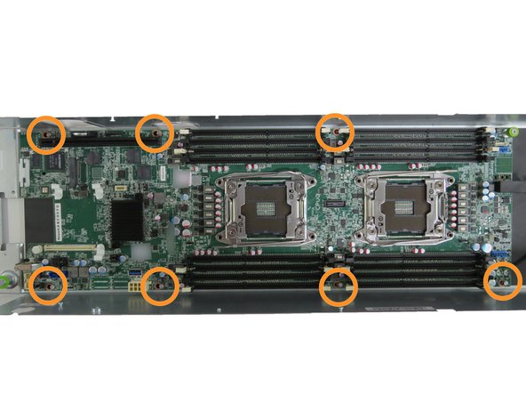
Push the motherboard towards the fans until (7) motherboard standoffs clear the motherboard guides.
-
-
-
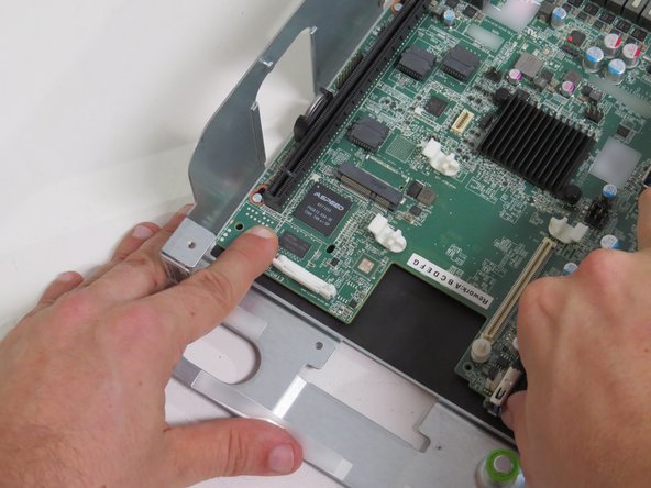
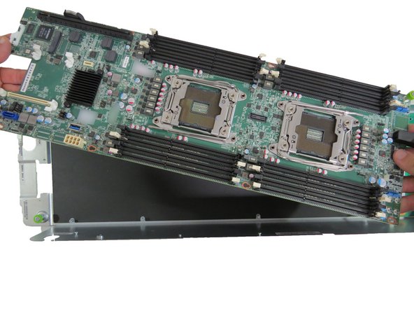
Lift the motherboard from the server chassis.
-
Slight wiggling may be required in order to clear the (7) standoffs.
-
-
-
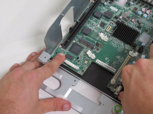
Place the motherboard in the server chassis,
-
Make sure all (7) chassis motherboard standoffs clear the motherboard guides.
-
Pull the motherboard towards the front of the chassis until resistance is felt.
-
-
-
Tighten (1) motherboard thumbscrew.
-
-
-
Loosen the midplane thumbscrew.
-
Slide the midplane board back to the motherboard interface.
-
Tighten the midplane thumbscrew.
-
-
-
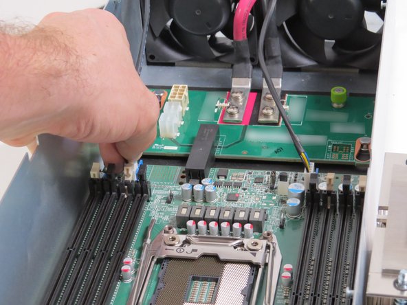
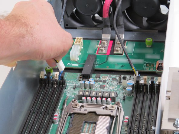
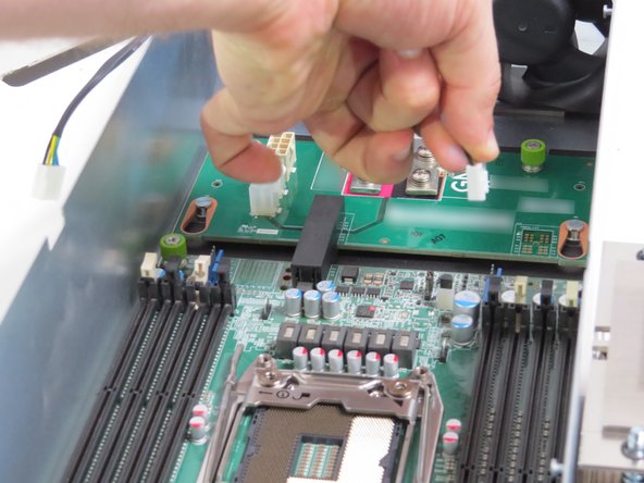
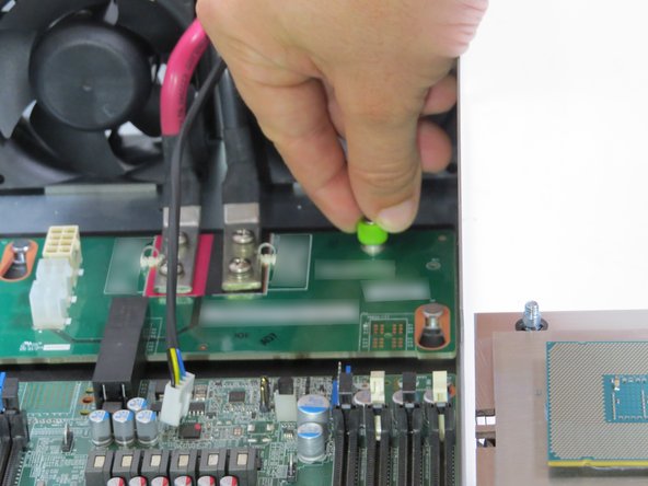
Connect two fan power connectors to the motherboard.
-
-
-
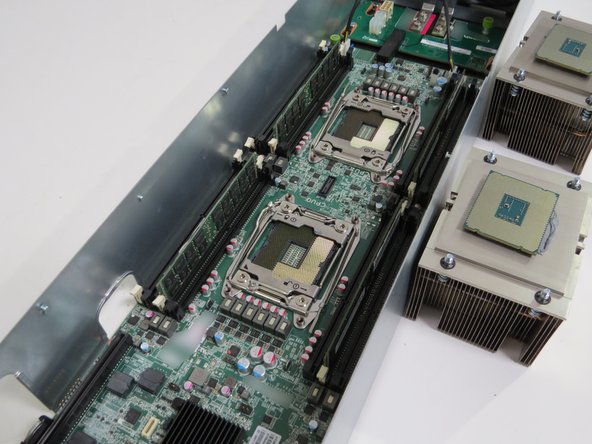
Connect all the DIMMs into the identical slots they were previously removed from.
-
-
-
Install (2) CPUs.
-
[invalid guide link]
-
-
-
Install (2) CPU heatsinks.
-
[invalid guide link]
-
-
-
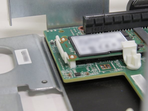
Connect the mSATA drive back into its socket.
-
Press down on the mSATA drive until the white nylon retention clip secures the mSATA drive.
-
A 'click' can be felt when the mSATA drive is properly seated.
-
-
-
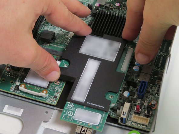
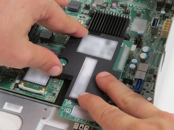
Connect the NIC onto the motherboard.
-
Lightly press the black film of the NIC until all (4) nylon standoffs secure the NIC to the motherboard.
-
-
-
Connect the HDD power and SATA cable connectors to the motherboard.
-
-
-
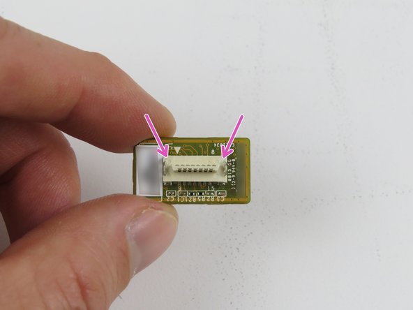
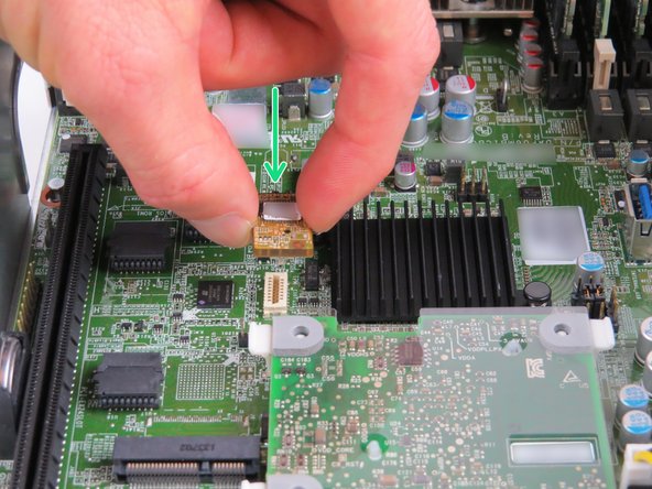
The TPM module and socket are keyed. Ensure that both are aligned prior to installation.
-
Once the TPM module connector has been aligned, insert it into the socket until resistance is felt.
-
-
-
Install the riser card assembly into the server.
-
Align chassis keys with the riser card assembly guides, as shown.
-
Press the riser card assembly down (most near the riser card PCB) until a 'click' is felt.
-
-
-
Tighten (2) thumbscrews on the riser card assembly, as shown.
-
-
-
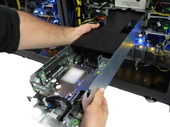
Install the lid on the server, as shown.
-
-
-
Slide the server back into the rack.
-
Continue pushing the server until the server chassis pin secures the server.
-
A distinctive 'click' will be felt when the pin secures the server in the rack.
-
-
-
Connect the 10G network interface cable.
-
-
-
Press the power button.
-






![[invalid guide link]](https://d3t0tbmlie281e.cloudfront.net/igi/opencompute/jAj2bFRnXlEdxqi3.medium)



![[invalid guide link]](https://d3t0tbmlie281e.cloudfront.net/igi/opencompute/VoMYxXvPFZnUSpTf.medium)


This work is licensed under a Creative Commons Attribution 4.0 International License.
This work is licensed under a Creative Commons Attribution 4.0 International License.
