
-
-
Perform a warm shut down on the server. Run:
-
ssh -l root <hostname> shutdown -h now
-
-
-
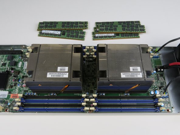
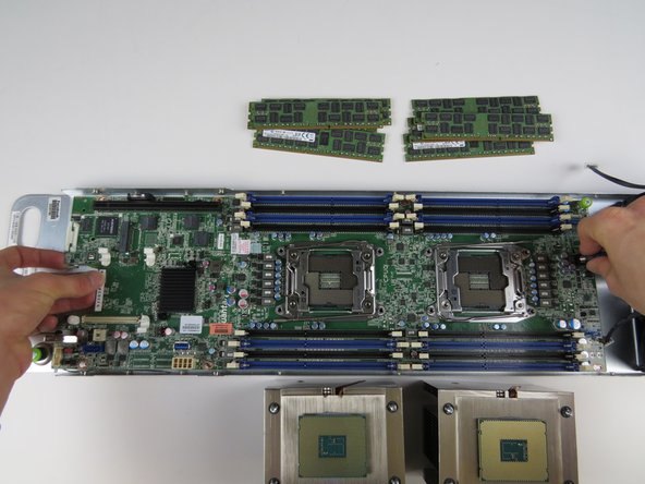
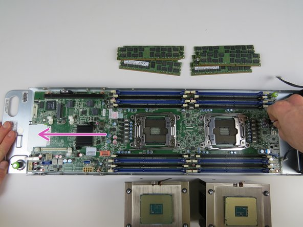
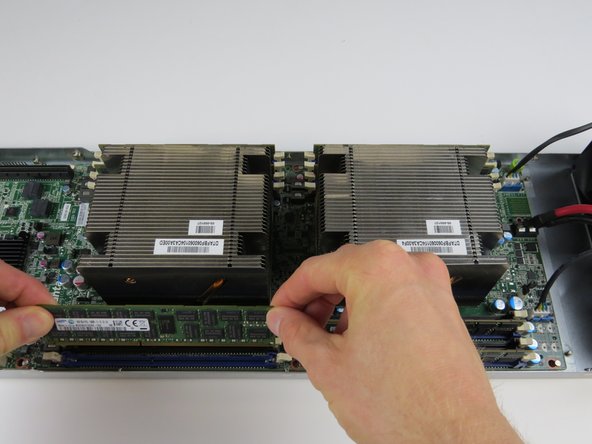
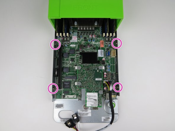
Disconnect and remove all the DIMMs.
-
Place all DIMMs aside for reuse with replacement motherboard.
-
-
-
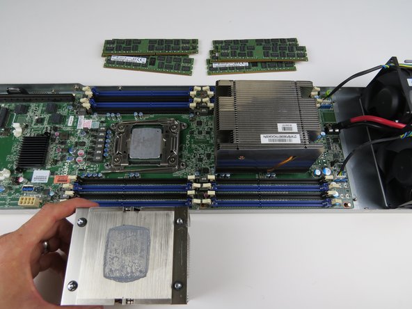
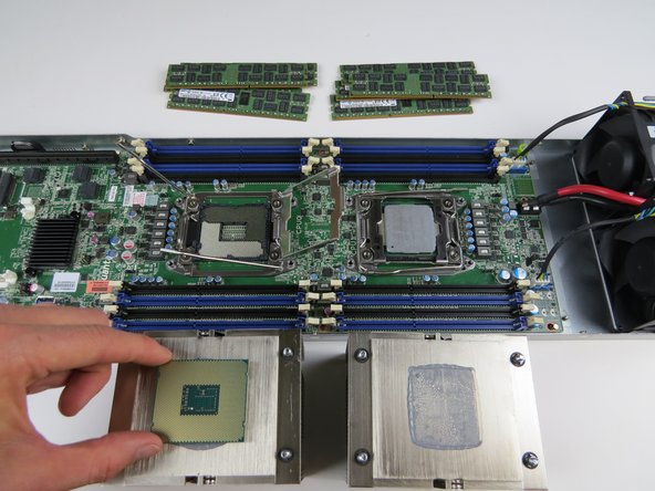
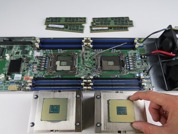
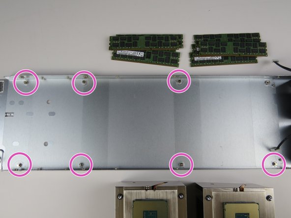
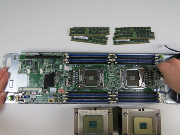
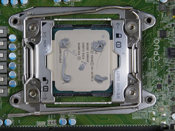
Remove (2) heatsinks and CPUs.
-
Place the CPUs on top of their respective heatsinks
-
-
-
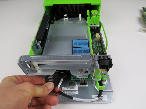
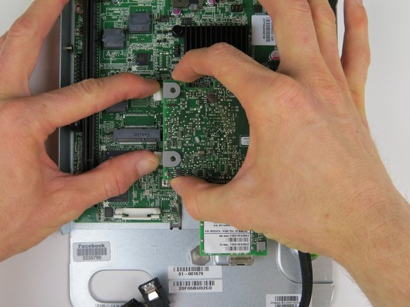
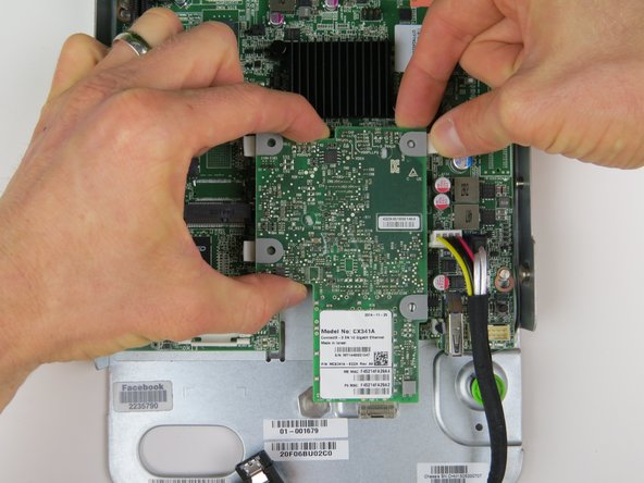
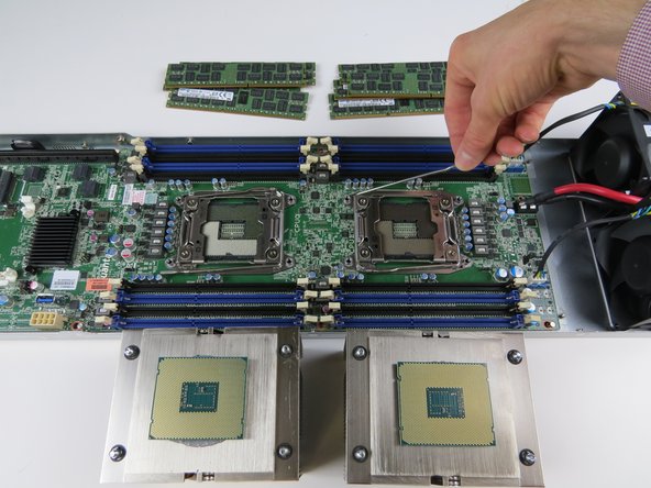
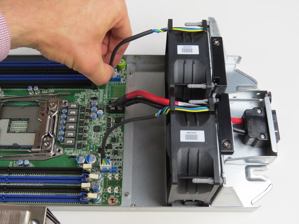
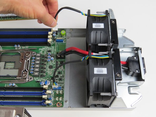
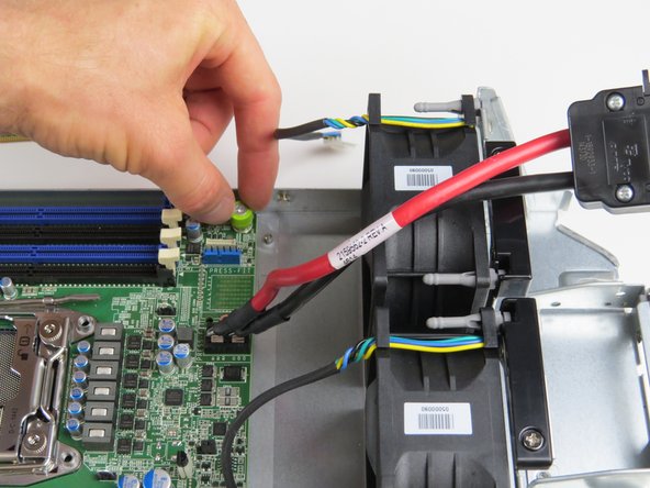
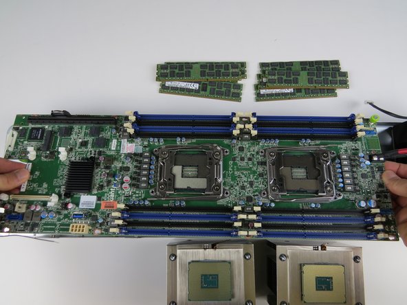
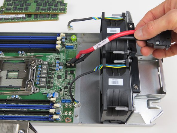
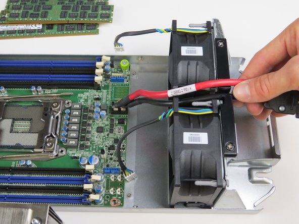
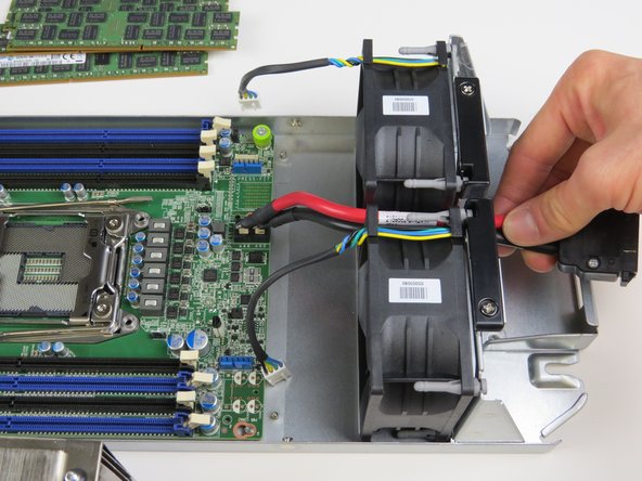
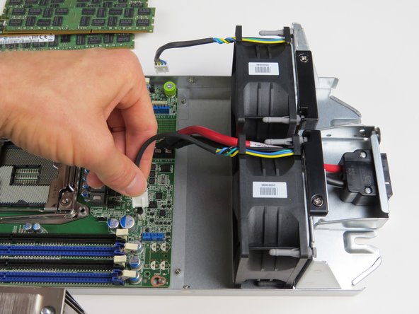
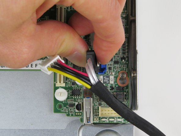
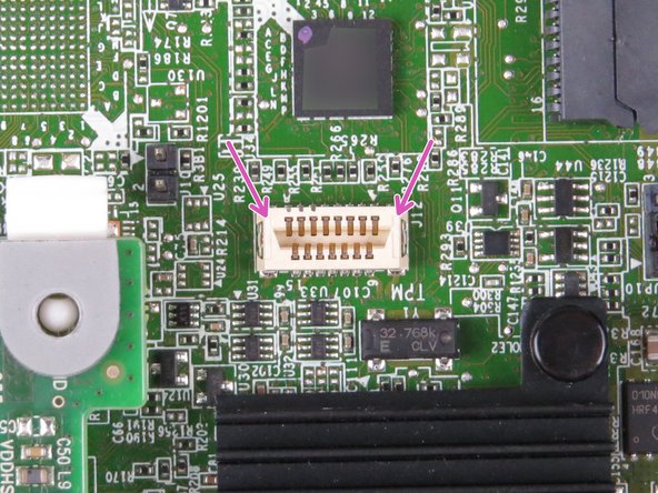
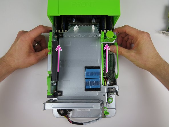
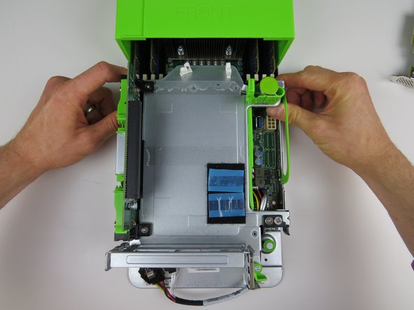
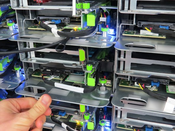
Connect (2) fan power cables.
-
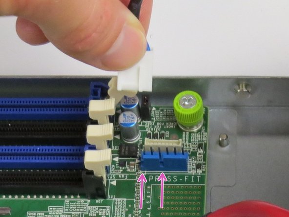
Make sure to align the key on the connector and header.
-
-
-
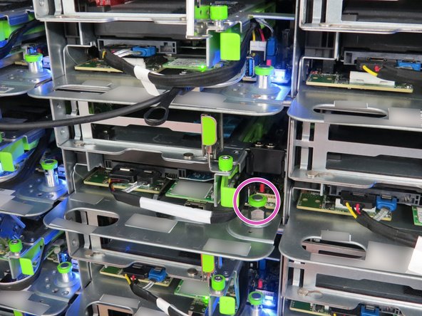
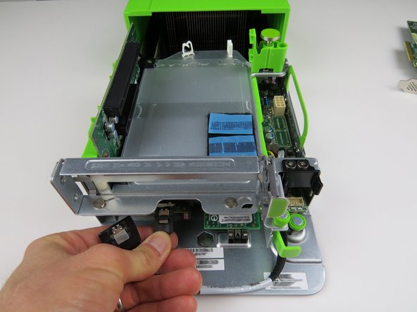
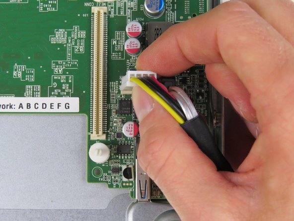
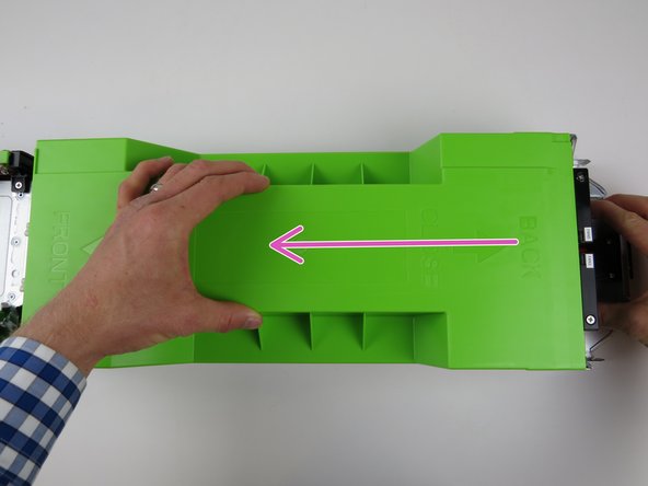
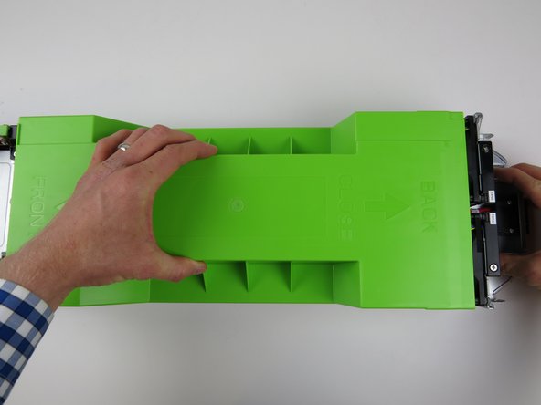
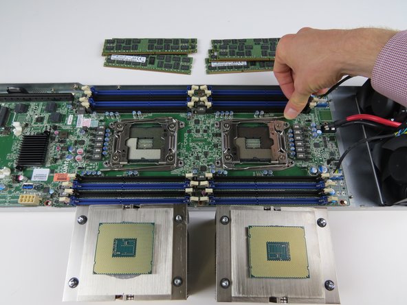
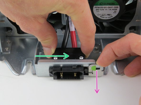
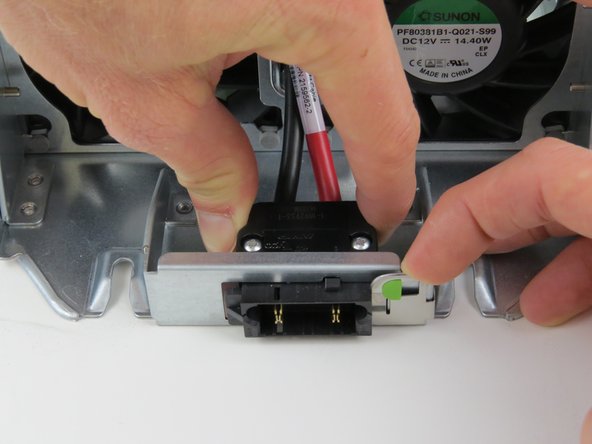
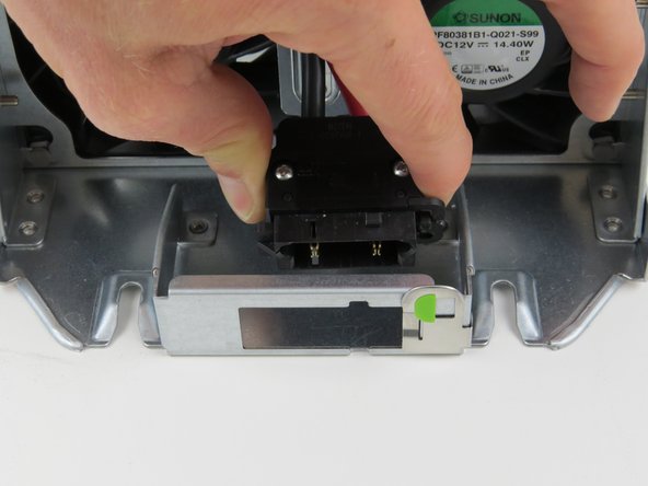
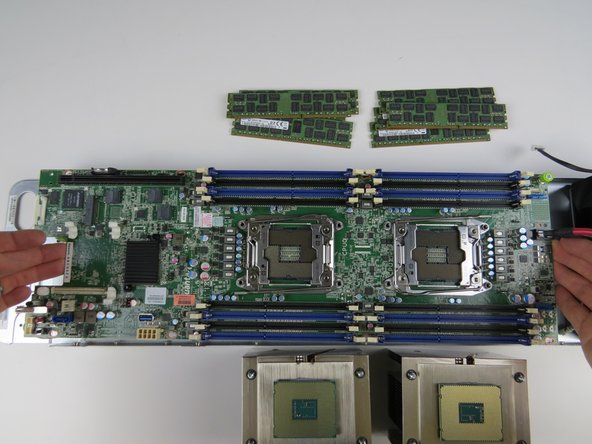
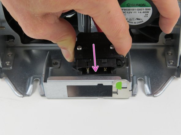
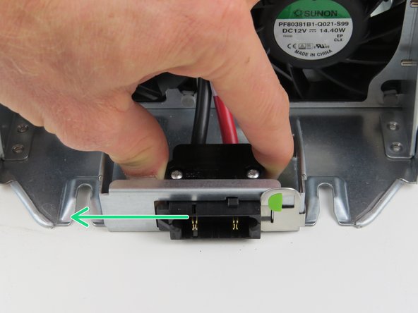
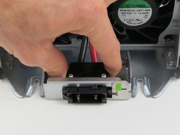
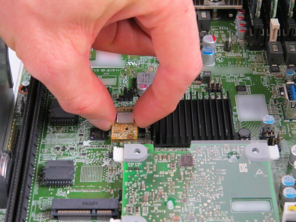
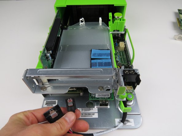
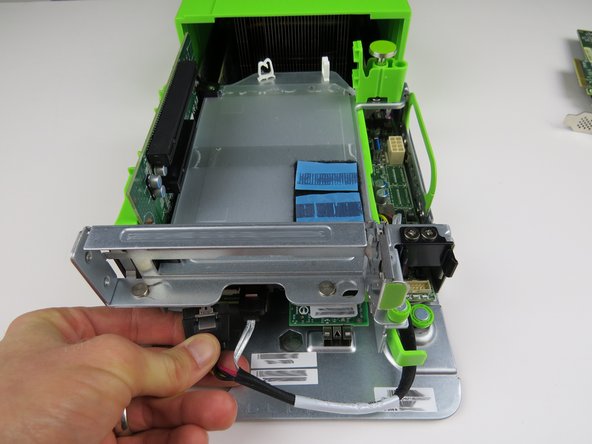
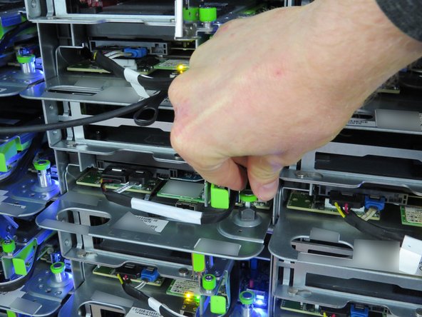
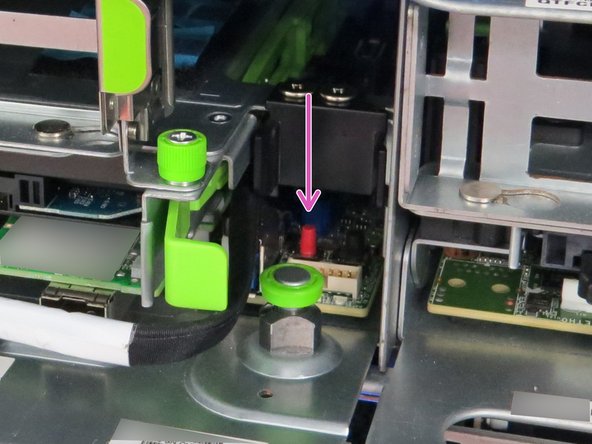
Insert the power connector into the slide-to-lock panel.
-
Once the connector has been inserted, slide it to the left to lock in place.
-
-
-
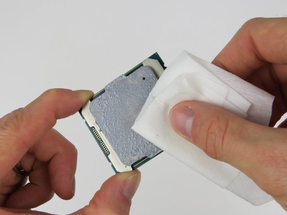
Prior to in CPU installation, thermal compound MUST be remove from BOTH the heatsink and CPU, then reapplied.
-
Utilize the 5-dot thermal compound method upon CPU installation.
-
-
-
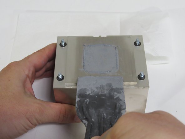
Scrape the thermal compound from the heatsink using a plastic putty knife.
-
Scrape parallel to the machined grain, as shown.
-
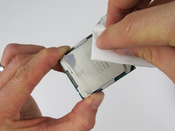
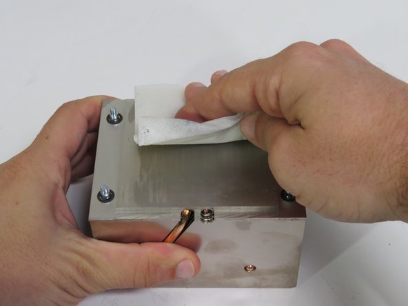
Wipe the remaining thermal compound off of the heatsink with an ispropyl alcohol pad.
-
Wipe parallel to the machined grain, as shown.
-
Continue this process until no thermal compound residue remains on the heatsink.
-
-
-
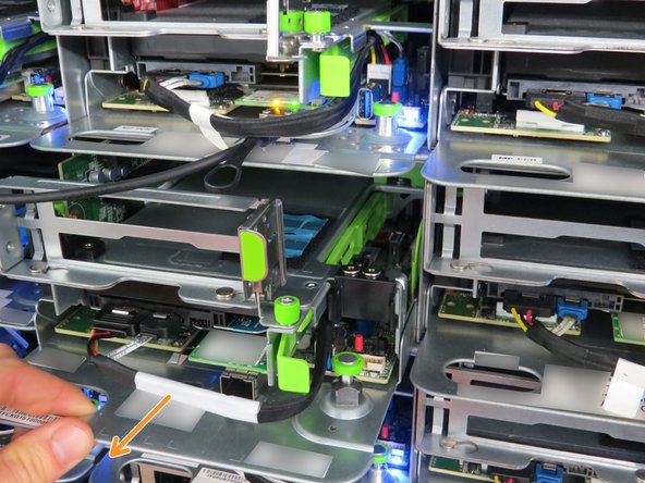
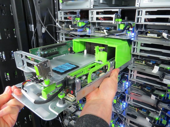
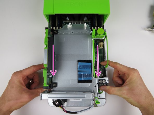
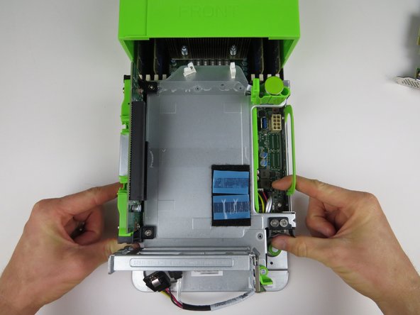
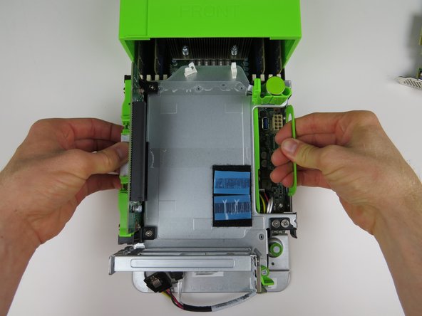
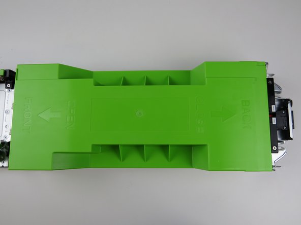
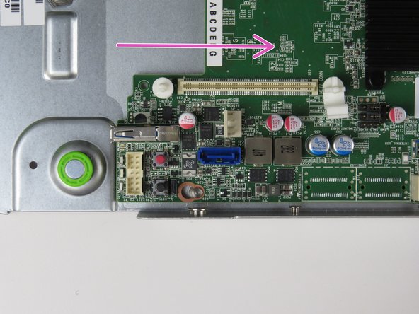
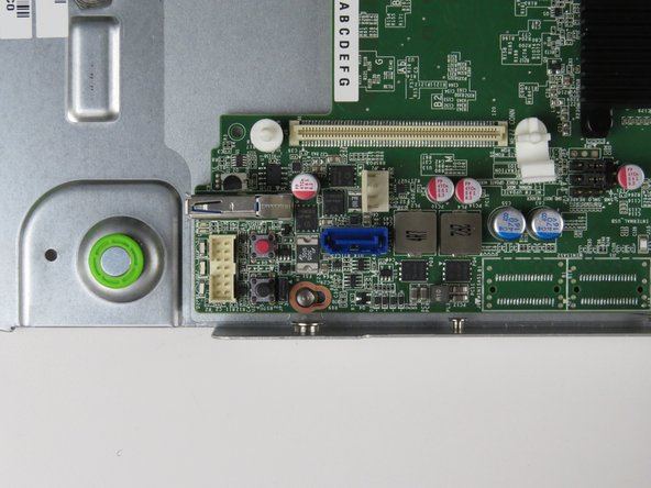
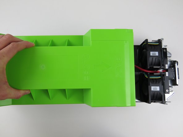
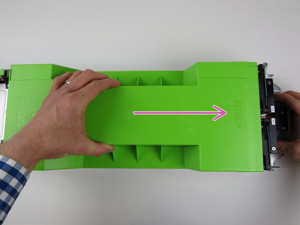
Insert the server sled into the rack as shown.
-
If the green retention plunger is still in the upright position, twist it 90 degrees to release it. This will secure the server.
-


This work is licensed under a Creative Commons Attribution 4.0 International License.
This work is licensed under a Creative Commons Attribution 4.0 International License.
