
Introduction
Overview
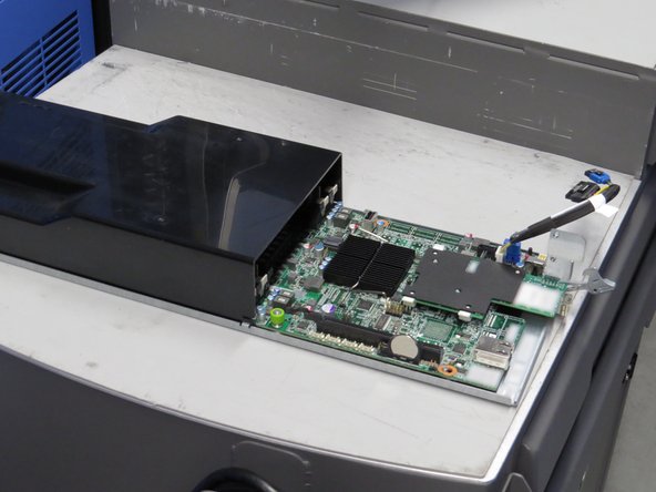
This guide demonstrates how to replace the system motherboard in an Open Compute V2 server. == Acronyms and Terms == * CPU - Central Processing Unit * DIMM - Dual In-line Memory Module * SATA - Serial ATA; a type of computer bus interface * SFP+ - Enhanced Small Form-factor Pluggable; a type of hot-plug transceiver
-
-
The server can be powered off remotely or on the hardware itself.
-
Remote Power Down: Login to the server to power it off.
-
shutdown -h now;exit -
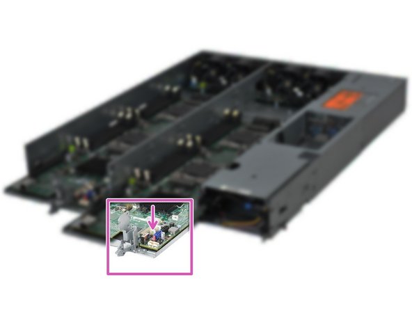
Hardware Power Down: Press and hold the power switch for at least three seconds, as annotated.
-
-
-
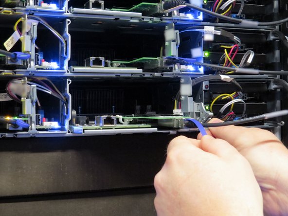
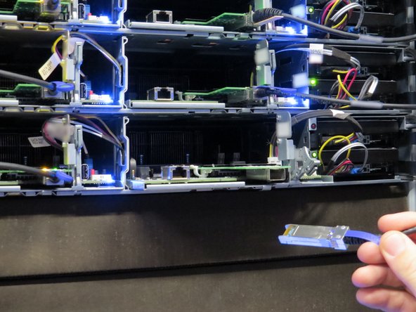
Disconnect the 10G SFP+ cable from the network interface controller.
-
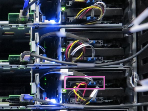
Disconnect the SATA / power cables connected to the boot hard disk drive.
-
Node 1 (right-most sled) boot drive is the top drive in the chassis. Node 0 (left-most sled) boot drive is the bottom drive in the chassis.
-
Disconnecting the SATA / power cable can be performed on either the motherboard or HDD end of server node 1 . However, the SATA / power cable must be disconnected from the motherboard end on node 0.
-
-
-
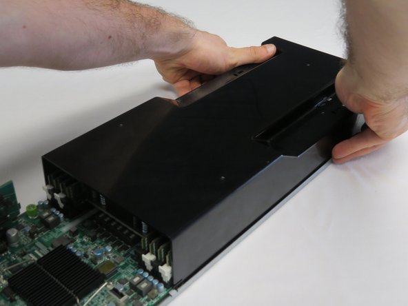
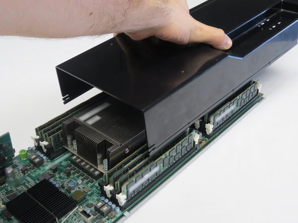
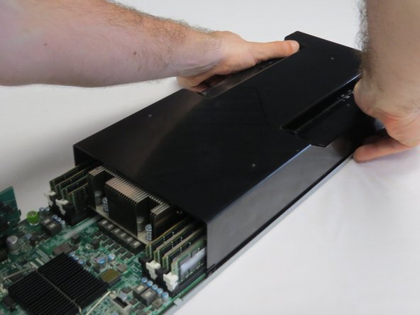
Engage the lid as shown.
-
Push the lid towards the rear of the server.
-
Lift the lid upwards when resistance is felt.
-
-
-
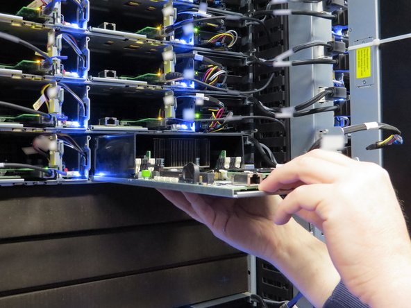
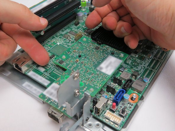
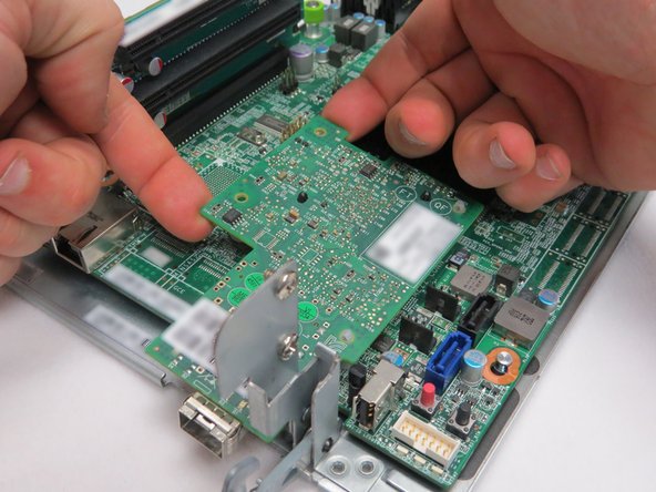
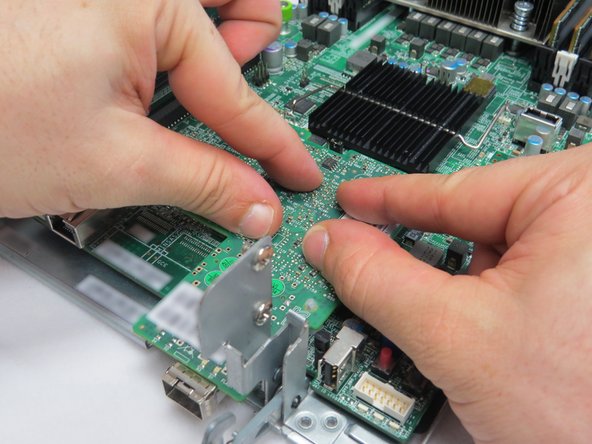
Place your fingers underneath the left side of the NIC PCB as shown.
-
Push the NIC up.
-
If the NIC cannot be pushed upwards, it may be necessary to use a tool (such as pliers) to pinch the arrowhead portion of the nylon standoffs.
-
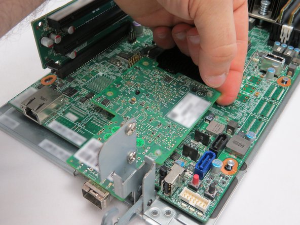
Push the top right corner up.
-
-
-
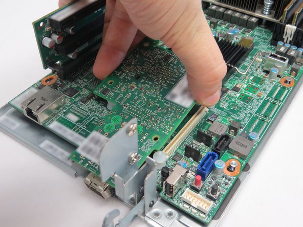
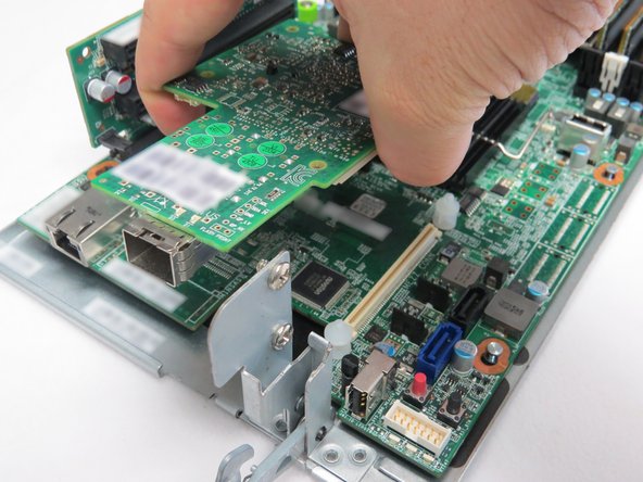
Grasp the NIC as shown.
-
Lift the NIC away from the server motherboard.
-
Place the NIC aside. It will be reinstalled at a later point in the procedure.
-
-
-
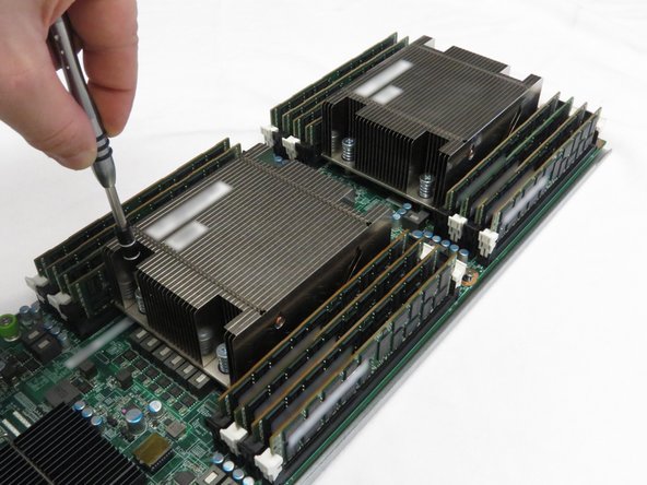
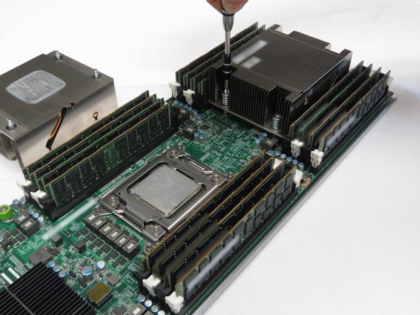
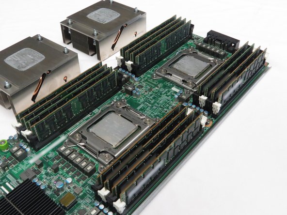
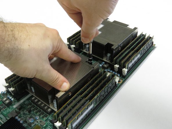
Using a cross-torque technique, loosen the Phillips #2 screws in a diagonal pattern to disconnect the CPU heatsinks from the motherboard.
-
-
-
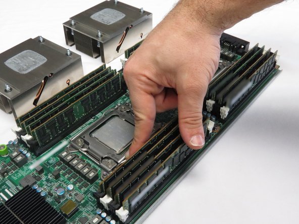
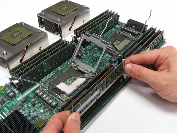
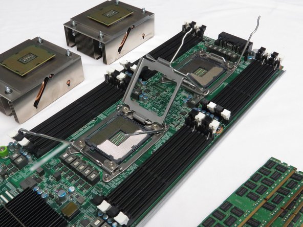
Press downwards on the DIMM retention tabs.
-
Remove each DIMM from its respective slot.
-
Make sure the DIMM pins do not contact any surface.
-
-
-
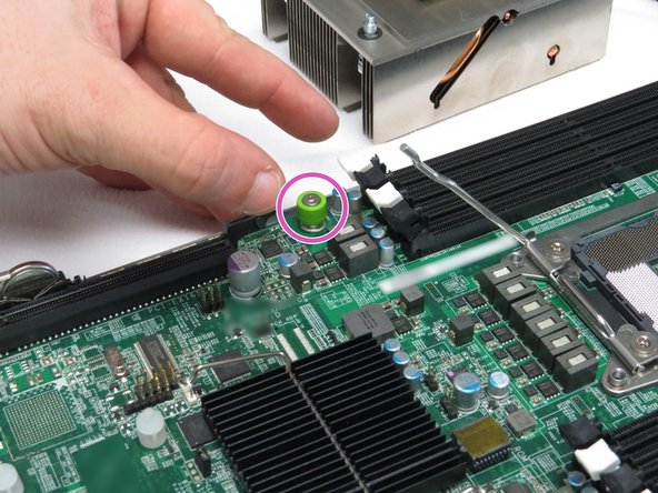
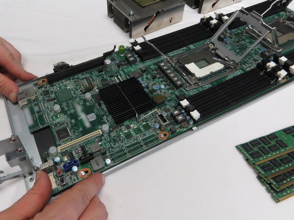
Loosen the thumbscrew shown.
-
This is the only thumbscrew securing the motherboard to the Open Compute V2 sled.
-
-
-
Remove the packaging from the new motherboard.
-
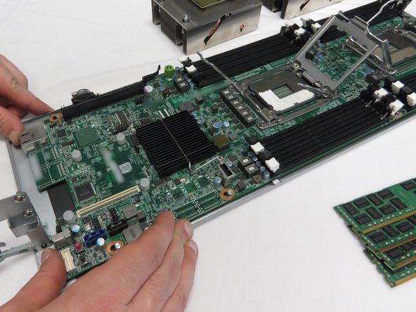
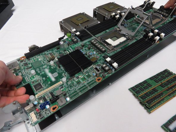
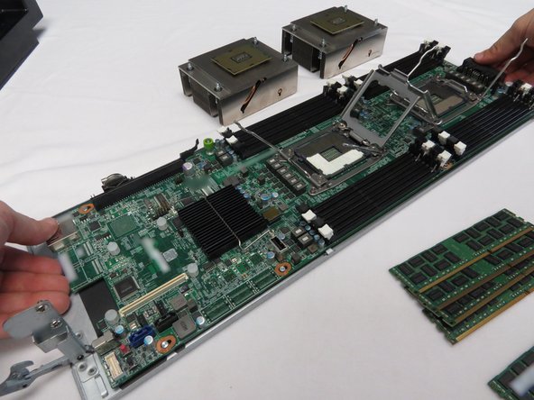
Place the motherboard on the standoffs / guides.
-
Push the motherboard towards the front of the server sled.
-
-
-
Update your systems configuration to account for the new Motherboard MAC address.
-
-
-
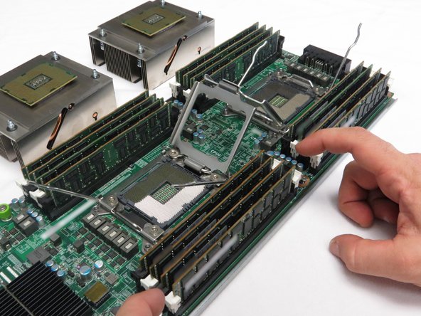
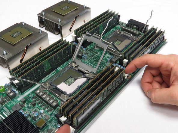
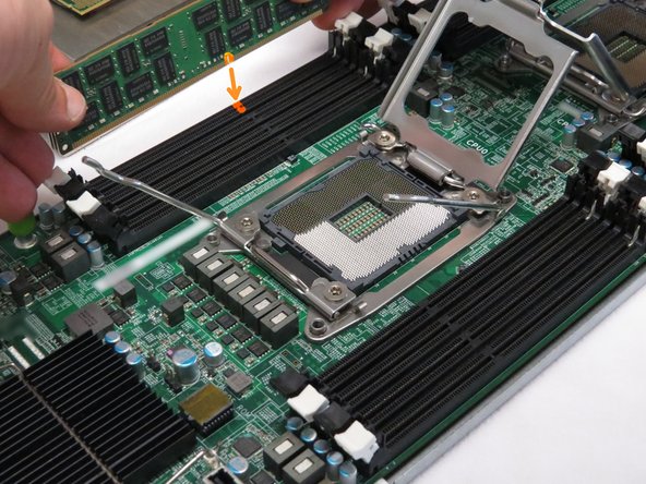
Align the DIMM pins with its socket key.
-
Press the DIMM down into the slot until the retention tabs spring upward to secure the module.
-
Repeat for the remaining DIMM.
-
-
-
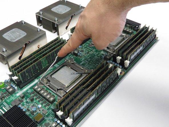
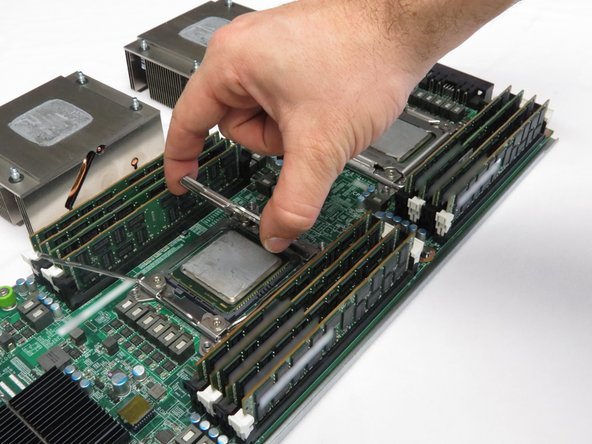
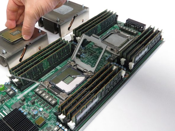
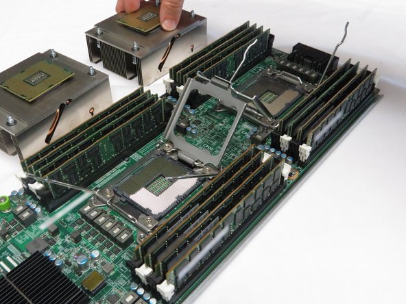
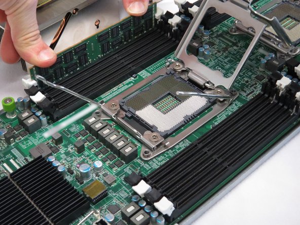
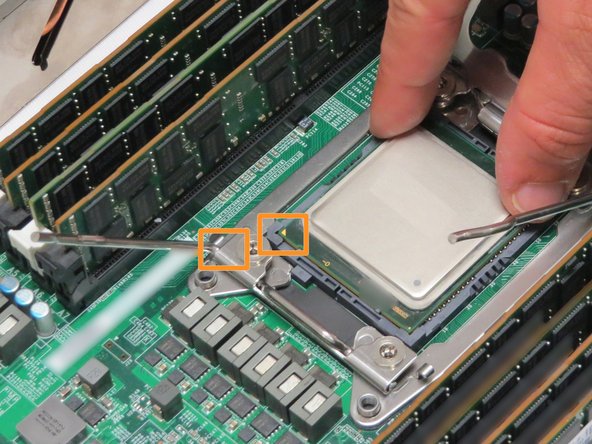
Align the CPU with its socket orientation, as shown.
-
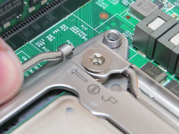
An arrow exists on both the CPU module and CPU retention gate. Align these corners.
-
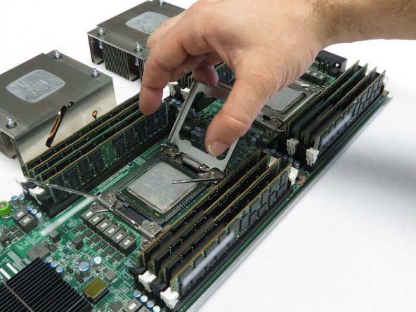
Carefully lower the CPU into its socket.
-
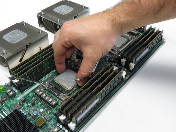
Close and secure the CPU retention gate.
-
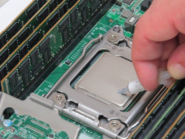
If thermal compound was removed for this application, apply thermal compound to the CPU.
-
Repeat this step for the remaining CPU.
-
-
-
Using a cross-torque technique, tighten the Phillips #2 screws in a diagonal pattern to install the CPU heatsinks onto the motherboard.
-
-
-
Place the NIC on the four nylon risers.
-
Push the NIC downwards.
-
The risers will make a distinctive 'click' when the card is properly seated.
-
-
-
Install the lid onto the server node.
-
The lid installation process is opposite of its removal process.
-


This work is licensed under a Creative Commons Attribution 4.0 International License.
This work is licensed under a Creative Commons Attribution 4.0 International License.

2 Comments
you given such a great info about motherboards and cpus ,The motherboard is a computer's central communications backbone connectivity point, through which all components so this very important to understand how its works so thanku guys for sharing this
josephjohn - Resolved on Release Reply