
Introduction
Overview
This guide demonstrates how to replace a power shelf in an Open Rack. == Acronyms and Terms == * AC - Alternating Current * DC - Direct Current * Tap Box - A service box with electrical interconnects. Tap boxes typically include circuit breakers. === Additional Notes === Safety: To prevent injury or death, it is crucial to de-energize the Open Rack's bus bars.
-
-
De-energize the rack.
-
Disconnect the rack's AC and DC circuit from your facilities electrical tap box.
-
Verify that no voltage is present on the rack's DC power rail before proceeding!
-
-
-
Do not touch the bus bars before removing power from the rack!
-
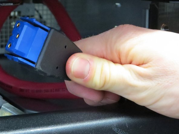
The power cable is located at the rear-right of the Open Rack.
-
Engage the two plastic clips on the power cable and disconnect it.
-
-
-
Make sure there is not live power on the bus bars before proceeding with this procedure.
-
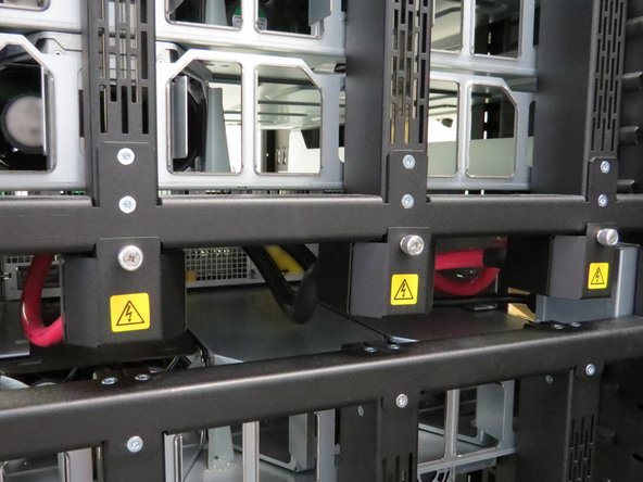
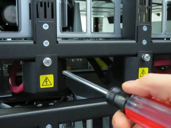
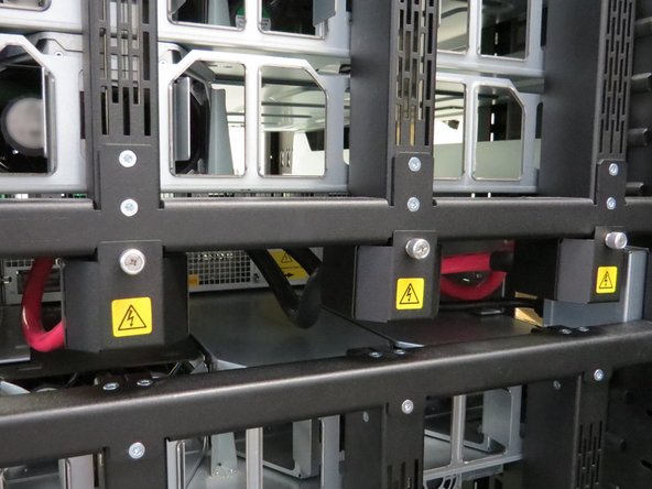
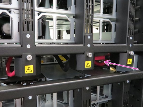
Loosen the three thumbscrews securing the bus bar lead shrouds to the rack.
-
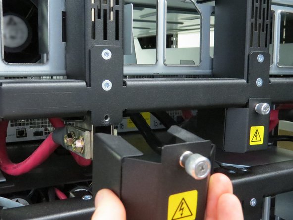
Remove the bus bar lead covers.
-
-
-
Go to the front of the Open Rack.
-
Disconnect and remove all power supply units located on the front of the rack.
-
This step further reduces potential of electrical shock risk.
-
-
-
Go to to the rear of the Open Rack.
-
Do not touch the bus bars.
-
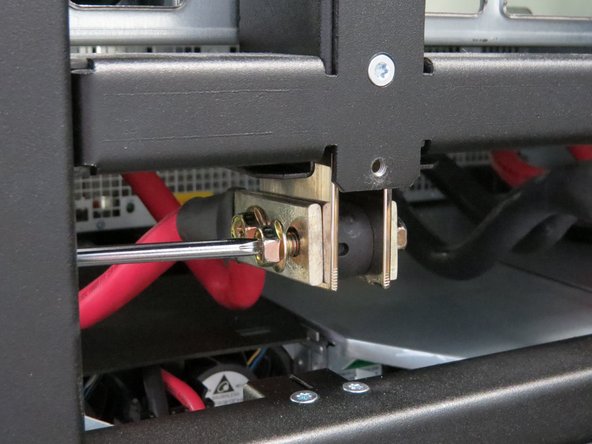
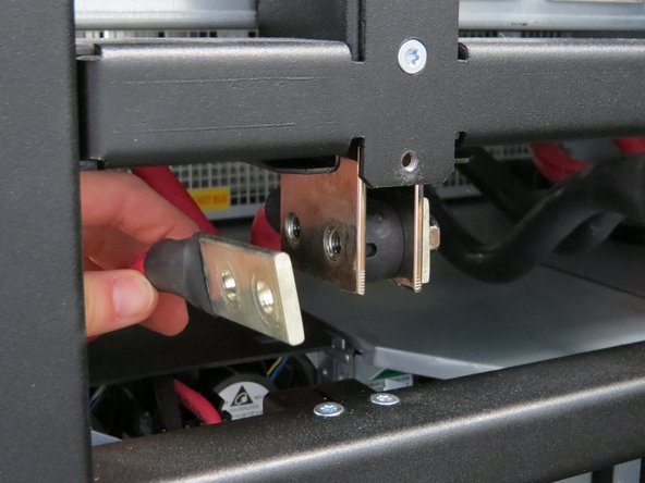
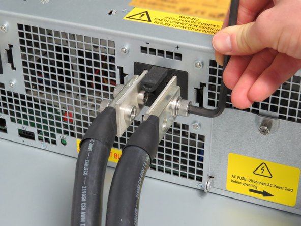
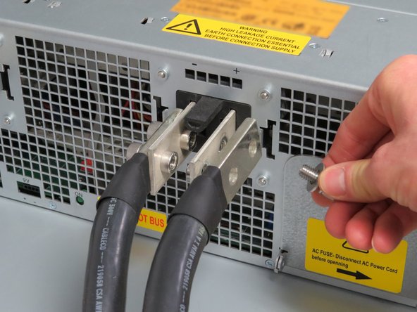
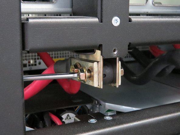
Remove the two Phillips #2 screws securing each lug cable to the Open Rack.
-
Some models have 5mm hex bolts. A 5mm hex wrench will be required to remove these bolts.
-
-
-
Do not touch the bus bars.
-
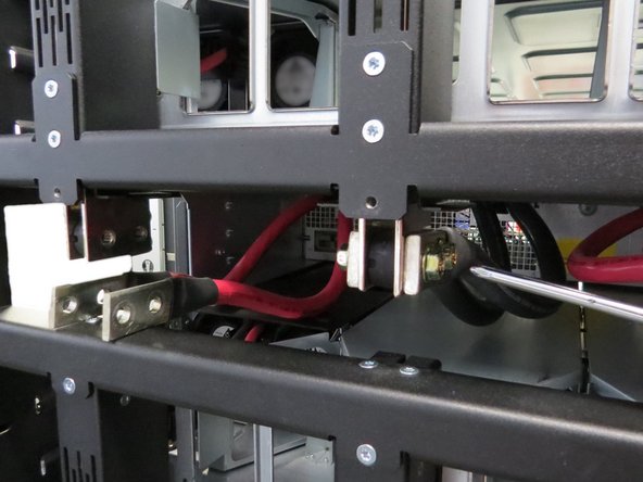
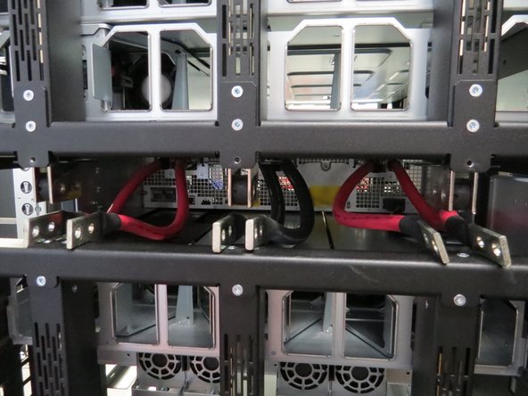
Continue disconnecting the left and right lug cables.
-
There are six lug cables that that should be disconnected form the rack.
-
-
-
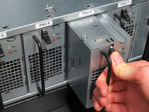
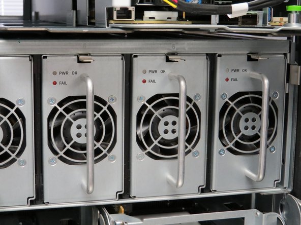
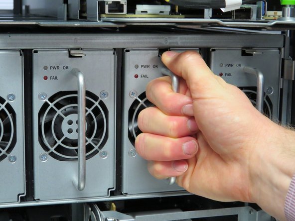
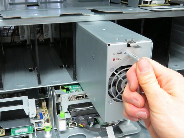
Locate the retention tab at the top of the power module unit.
-
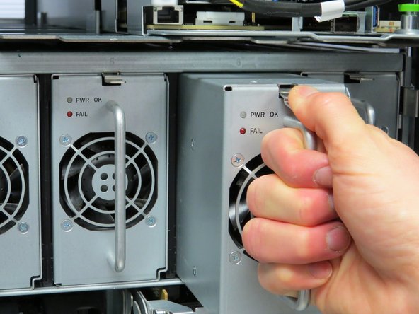
Press the retention tab down and pull the power supply outwards to remove it.
-
Remove all of the power supplies and place aside for later installation.
-
-
-
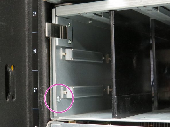
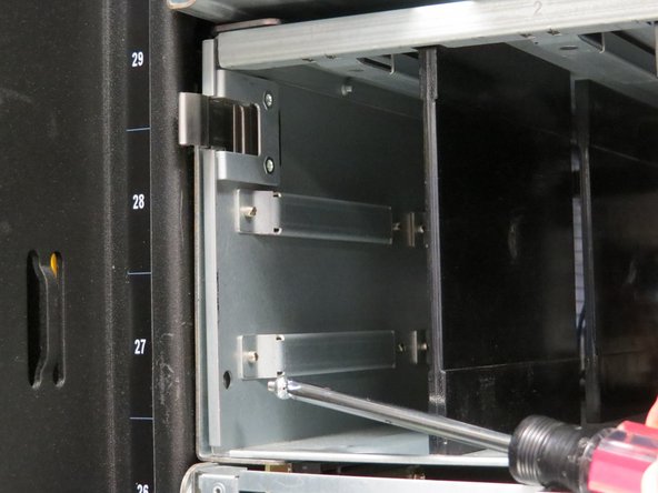
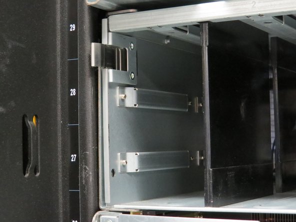
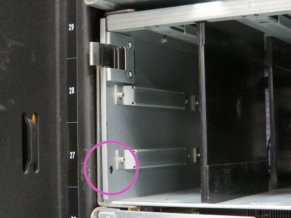
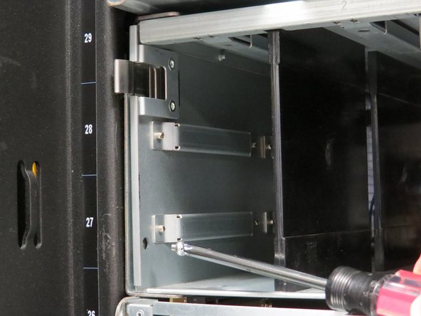
Remove the Phillips #2 screw located on each side of the power shelf.
-
These are safety screws to secure the power shelf. There are two safety screws in total.
-
-
-
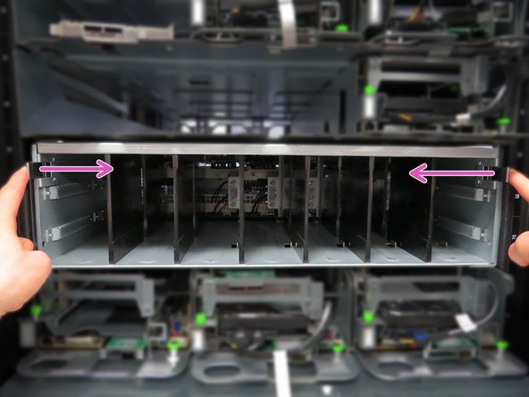
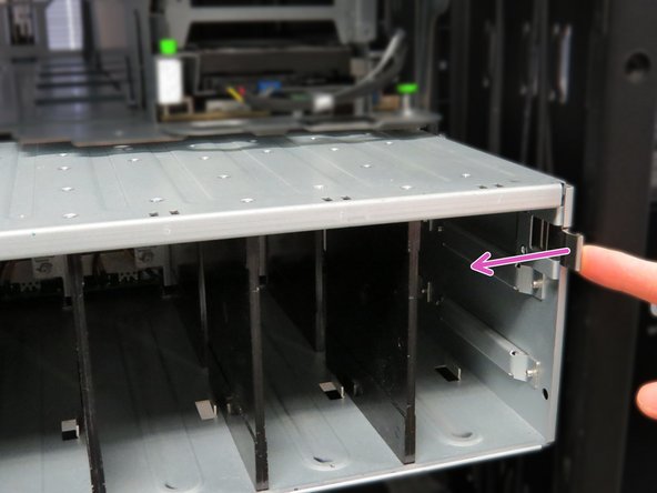
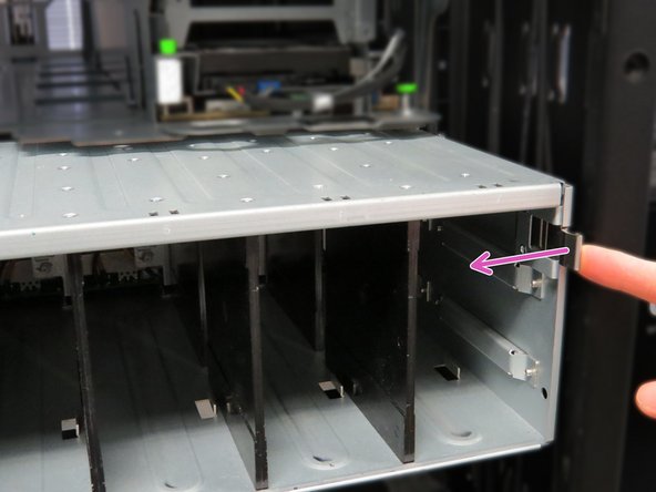
Press the two shelf retention tabs inwards.
-
After sliding the shelf out about 8cm, press the tabs inwards again to avoid contact with the rack chassis.
-
-
-
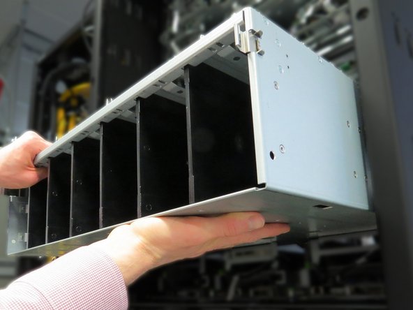
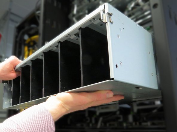
Place your hand underneath the shelf to counter the weight of the shelf.
-
Move the shelf to a workbench.
-
-
-
Disconnect the power lug cables using a 5mm Allen wrench.
-
There are six lug cables and twelve screws.
-
-
-
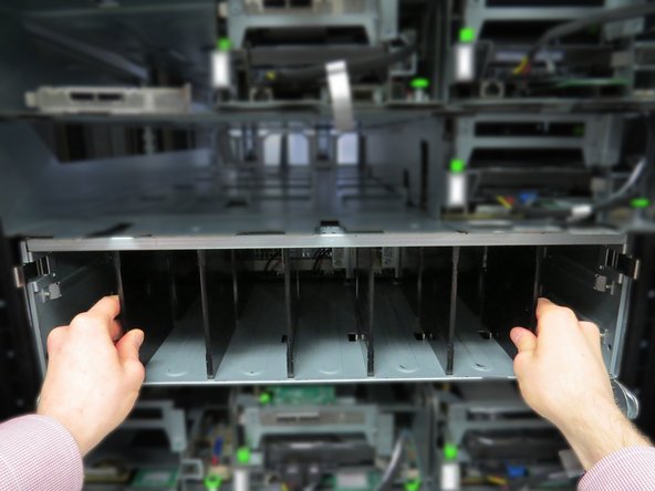
Insert the shelf into the rack.
-
Locate and press two tabs on each side of the power shelf.
-
Continue sliding the shelf into the rack.
-
The retention tabs will lock and make a distinctive 'click' when the shelf is secure.
-
-
-
Screw in the two safety screws that were previously removed.
-
-
-
Do not touch the bus bars.
-
Connect the lug cables that were previously disconnected.
-
Some models have 5mm hex bolts. A 5mm hex wrench will be required to remove these bolts.
-
There are a total of six lug cables to connect.
-
-
-
Do not touch the bus bars.
-
Install the three bus bar lead covers that were previously removed.
-
-
-
Install all of the power supply units that were previously removed.
-
The power supply is seated correctly when the retention tab snaps upward.
-
-
-
Do not touch the bus bars.
-
Connect the power cable to the power shelf.
-






This work is licensed under a Creative Commons Attribution 4.0 International License.
This work is licensed under a Creative Commons Attribution 4.0 International License.
