
Introduction
Overview
This guide is intended to be a resource for quickly installing and integrating a Wedge switch into your data center environment. == Acronyms and Terms == * AC - Alternating Current * AWG - American Wire Gauge * CAT5, CAT5e, CAT6 - Category Ethernet Cable Types * DAC - Direct Attach Copper * DC - Direct Current * ETSI - European Telecommunications Standards Institute * ETS - European Telecommunications Standards * LED - Light-Emitting Diode * PSU - Power Supply Unit * QSFP - Quad Small Form-factor Pluggable; a type of hot-pluggable data communications transceiver * VDC - A unit measurement of DC Volts
Tools
No tools specified.
Parts
-
-
Remove the Wedge switch from its packaging.
-
Locate the Wedge rack mounting kit and place it to the side.
-
Find the system ground wire and place it to to the side.
-
The mounting kit and ground wire are required parts for first-time installation of the Wedge switch.
-
-
-
The Wedge requires either rack L-Brackets or a rack shelf for mounting the unit in the rack.
-
Attach the supplied brackets to each side of the switch.
-
Mount the switch in the rack and tighten two thumbscrews.
-
-
-
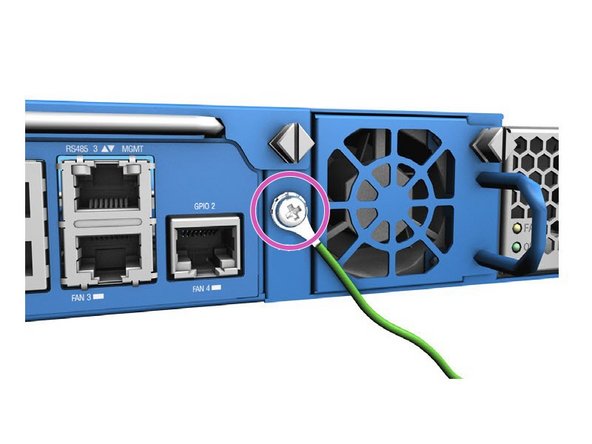
Caution: The ground connection should not be removed unless all power supply connections have been disconnected.
-
Connect the grounding wire to the grounding point on the rear panel of the switch.
-
Attach a ground lug to the 18 AWG minimum grounding wire.
-
Grounding wire and lug are not provided with AC powered Wedge assemblies.
-
Connect the other end of the grounding wire to the rack's grounding point.
-
Ensure no paint or isolating surface treatment exists on the rack side of the grounding point.
-
Ensure the rack is properly grounded and in compliance with ETSI ETS 300 253.
-
-
-
Warning: Before wiring the DC plug or connecting power to the switch, ensure power to the feed lines are turned off at the supply circuit breaker, or disconnected from the power bus.
-
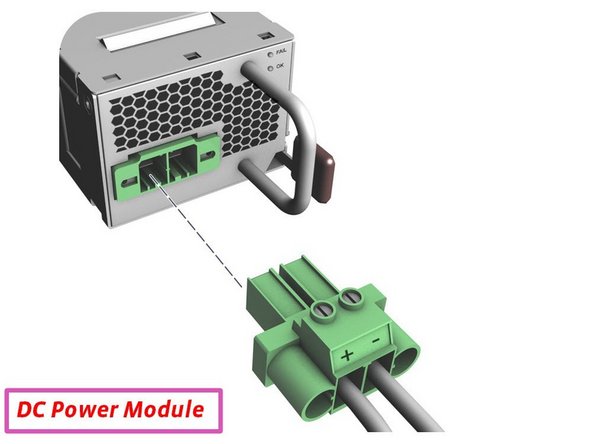
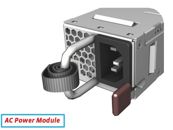
Install either two AC or DC power modules in the switch (depending on your environment's configuration).
-
Connect either an external AC or DC power source to the power modules (depending on your environment's configuration).
-
DC Power Module: Connect the external power feed and power ground / return lines to the DC plug. The -42 VDC power feed connect to the (-) pin, and the ground / return connects to the (+) pin.
-
AC Power Module: Unwind the Velcro strip before plugging in the AC power source. Use the Velcro strip to secure the AC cord to the PSU.
-
-
-
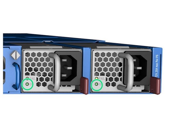
Verify that the switch has powered on by observing the PSU LEDs.
-
When operating normally, the
PSU OKLEDs will be on (green). -
Note: A power cable is required to verify whether the LEDs are on (not pictured in the image).
-
-
-
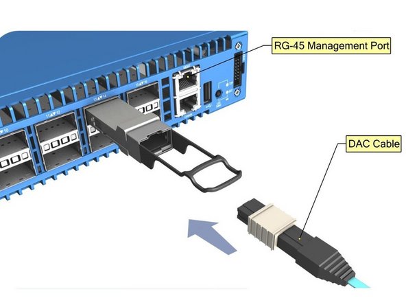
Connect a 100 ohm, CAT5, Cat-5e, or CAT6 cable to the RJ-45 management port.
-
Connect DAC to the QSFP+ ports.
-
Alternatively, one can install QSFP+ transceivers into the ports before installing the fiber optic lines.
-

This work is licensed under a Creative Commons Attribution 4.0 International License.
This work is licensed under a Creative Commons Attribution 4.0 International License.
