Introduction

Overview

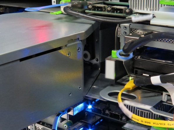
This guide demonstrates how to replace the RAID controller in an Open Compute V3 server node. == Acronyms and Terms == * Mini-SAS - Mini Serial Attached SCSI * SCSI - Small Computer System Interface * SFP+ - Enhanced Small Form-factor Pluggable; a type of hot-pluggable transceiver. * RAID - Redundant Array of Independent Disks

  1. The server can be powered off remotely or on the hardware itself.
    • The server can be powered off remotely or on the hardware itself.

    • Remote Power Down: Login to the server to power it off.

    • shutdown -h now;exit

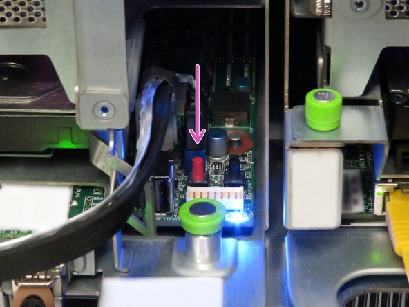
    • Hardware Power Down: Press and hold the power switch for at least three seconds, as annotated.

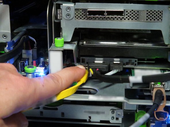
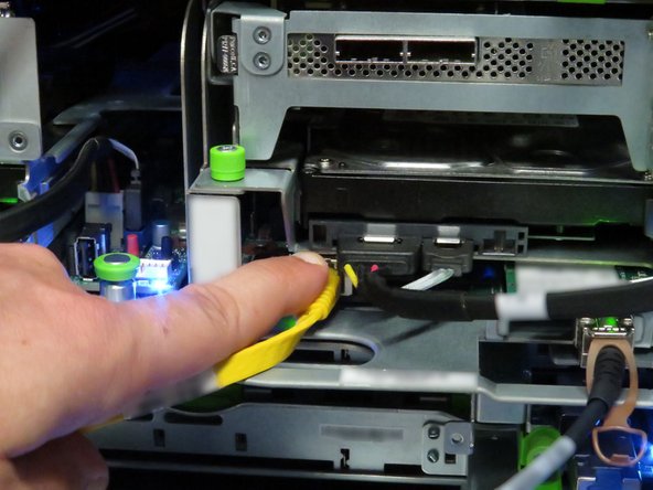
  2. Disconnect the Mini-SAS cable by pulling on the pull-tab, as shown. Disconnect the Mini-SAS cable by pulling on the pull-tab, as shown.
    • Disconnect the Mini-SAS cable by pulling on the pull-tab, as shown.

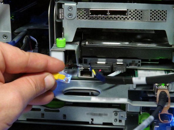
  3. Disconnect the Ethernet cable from the server. Press the tab on the end of the cable to release it.
    • Disconnect the Ethernet cable from the server.

    • Press the tab on the end of the cable to release it.

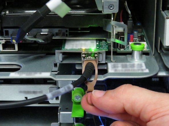
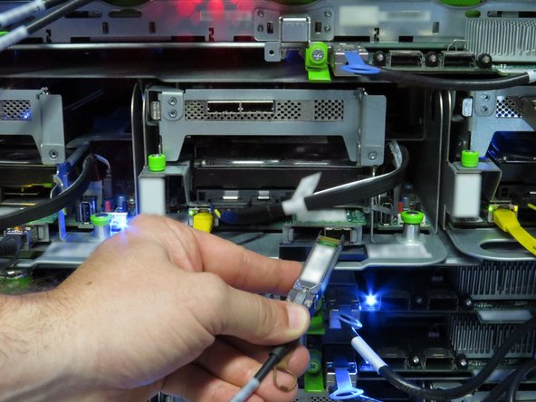
  4. Disconnect the 10G SFP+ cable by pulling on the pull-tab, as shown. Disconnect the 10G SFP+ cable by pulling on the pull-tab, as shown.
    • Disconnect the 10G SFP+ cable by pulling on the pull-tab, as shown.

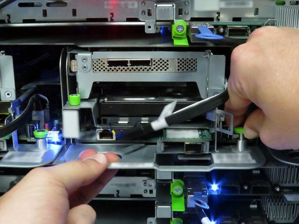
  5. Pull the retention plunger upwards. Grasp the server as shown. Remove the server from the rack.
    • Pull the retention plunger upwards.

    • Grasp the server as shown.

    • Remove the server from the rack.

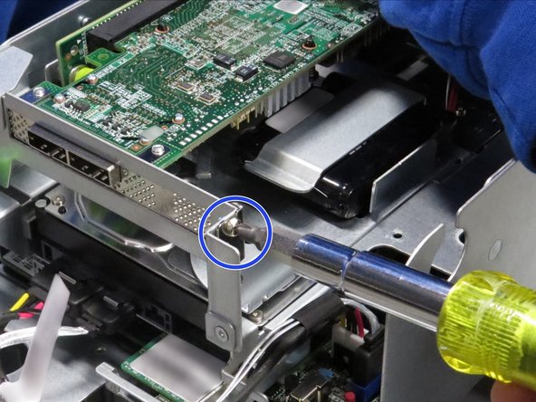
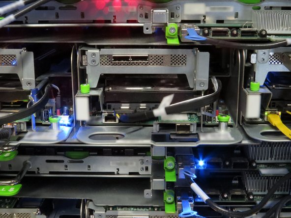
  6. Unscrew the Phillips #2 screw from the RAID controller bracket.
    • Unscrew the Phillips #2 screw from the RAID controller bracket.

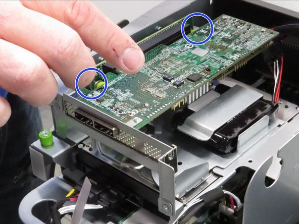
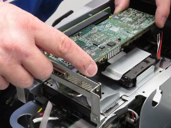
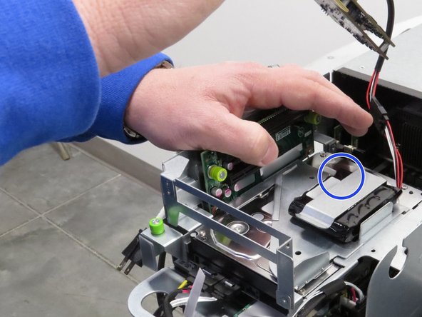
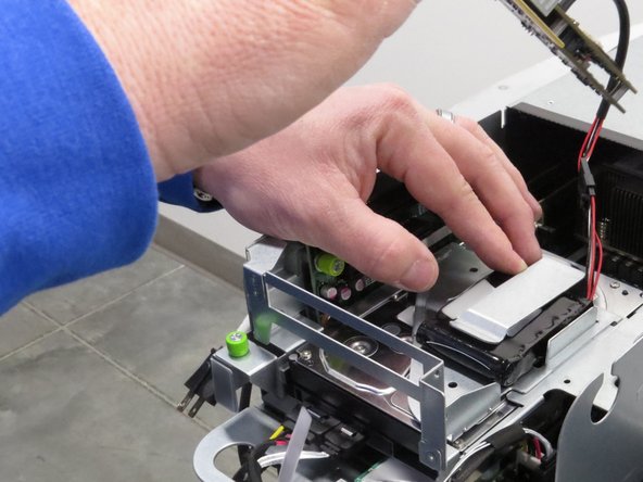
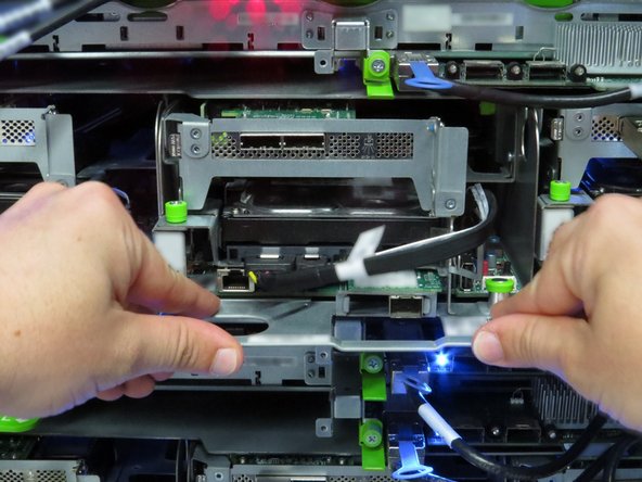
  7. Place your thumbs behind the RAID controller circuit board, as shown. Push the RAID controller away from the riser board socket. Push the RAID controller away from the riser board socket.
    • Place your thumbs behind the RAID controller circuit board, as shown.

    • Push the RAID controller away from the riser board socket.

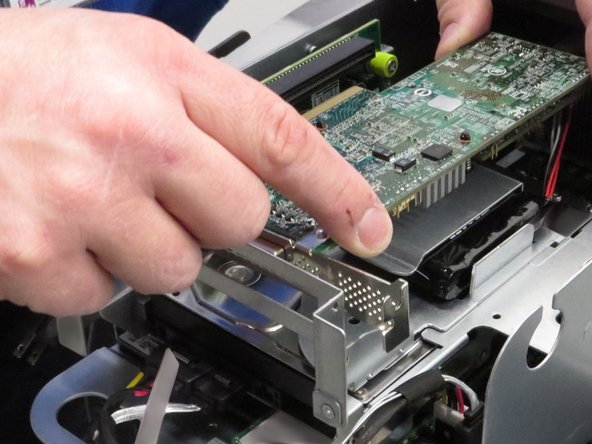
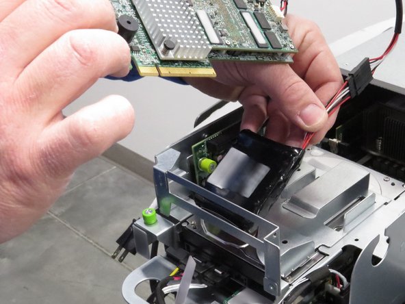
  8. Remove the battery pack with the RAID controller. Remove the battery pack with the RAID controller. Remove the battery pack with the RAID controller.
    • Remove the battery pack with the RAID controller.

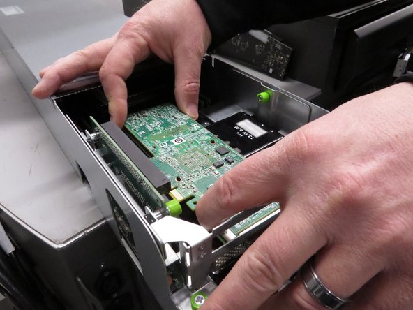
  9. Connect the RAID controller to its original PCIe socket.
    • Connect the RAID controller to its original PCIe socket.

    • Place the RAID controller pack in its original position.

  10. Screw in the Phillips #2 screw.
    • Screw in the Phillips #2 screw.

  11. Place the server in the slot where it was previously removed. Push the server into the slot. Do not use the chassis handle as it could pinch your hand.
    • Place the server in the slot where it was previously removed.

    • Push the server into the slot.

    • Do not use the chassis handle as it could pinch your hand.

  12. Connect the Ethernet cable to the RJ45 port on the server motherboard.
    • Connect the Ethernet cable to the RJ45 port on the server motherboard.

  13. Connect the 10G SFP+ cable to the network interface controller port. A distinctive 'click' will be audible when the cable is seated correctly.
    • Connect the 10G SFP+ cable to the network interface controller port.

    • A distinctive 'click' will be audible when the cable is seated correctly.

  14. Connect the Mini-SAS cable to the RAID controller.
    • Connect the Mini-SAS cable to the RAID controller.

  15. Press the power button.
    • Press the power button.

Conclusion

Dozuki System

Member since: 09/24/2009

1 Reputation

142 Guides authored

0 Comments

Add Comment

View Statistics:

Past 24 Hours: 0

Past 7 Days: 1

Past 30 Days: 5

All Time: 117