
Introduction
Overview
This guide demonstrates how to replace the RAID controller in an Open Compute V3 server node. == Acronyms and Terms == * Mini-SAS - Mini Serial Attached SCSI * SCSI - Small Computer System Interface * SFP+ - Enhanced Small Form-factor Pluggable; a type of hot-pluggable transceiver. * RAID - Redundant Array of Independent Disks
-
-
The server can be powered off remotely or on the hardware itself.
-
Remote Power Down: Login to the server to power it off.
-
shutdown -h now;exit -
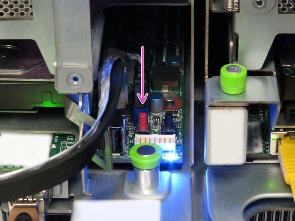
Hardware Power Down: Press and hold the power switch for at least three seconds, as annotated.
-
-
-
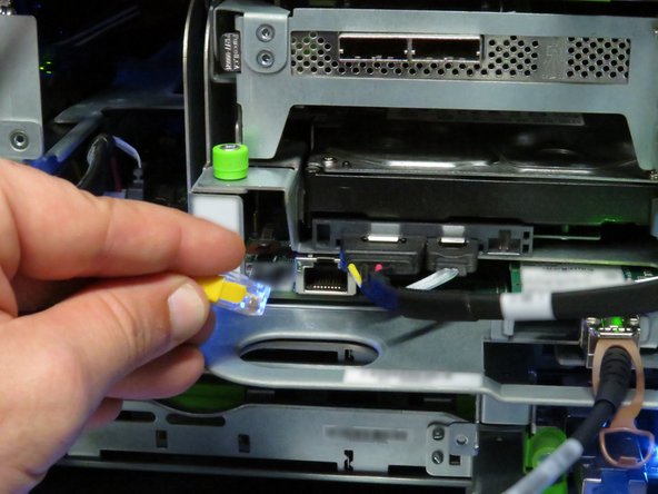
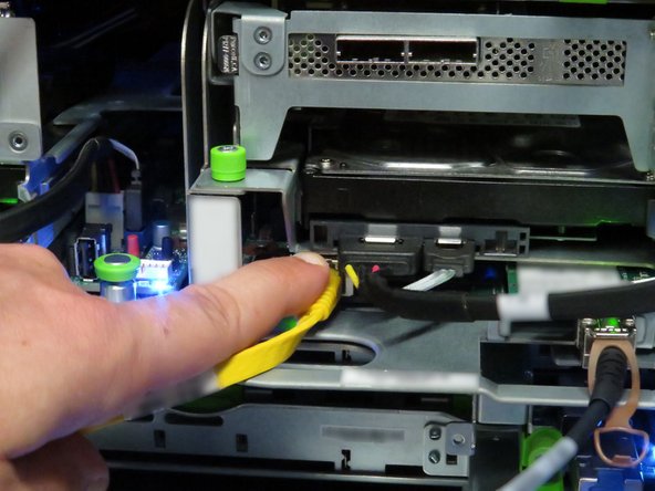
Disconnect the Mini-SAS cable by pulling on the pull-tab, as shown.
-
-
-
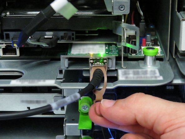
Disconnect the Ethernet cable from the server.
-
Press the tab on the end of the cable to release it.
-
-
-
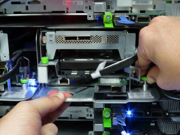
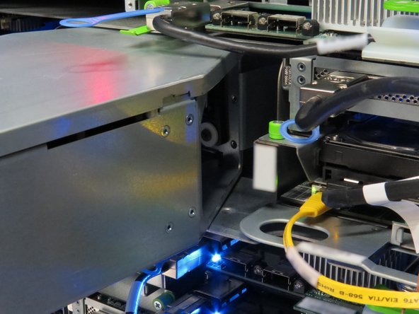
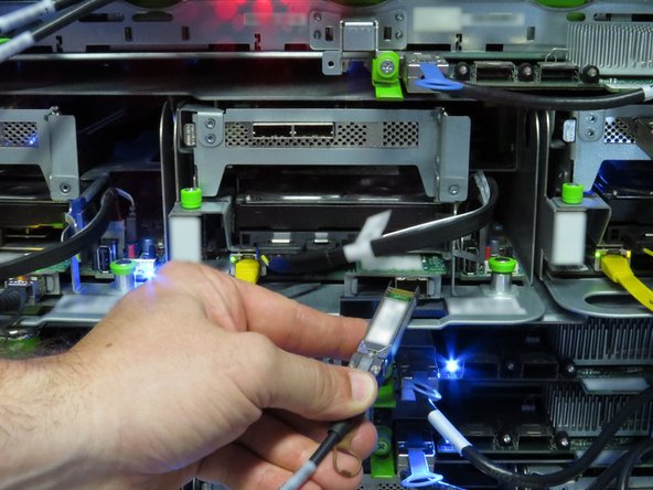
Disconnect the 10G SFP+ cable by pulling on the pull-tab, as shown.
-
-
-
Pull the retention plunger upwards.
-
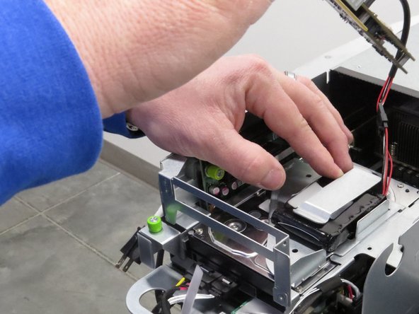
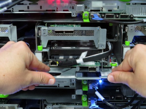
Grasp the server as shown.
-
Remove the server from the rack.
-
-
-
Place the server in the slot where it was previously removed.
-
Push the server into the slot.
-
Do not use the chassis handle as it could pinch your hand.
-
-
-
Connect the Ethernet cable to the RJ45 port on the server motherboard.
-


This work is licensed under a Creative Commons Attribution 4.0 International License.
This work is licensed under a Creative Commons Attribution 4.0 International License.
