
-
-
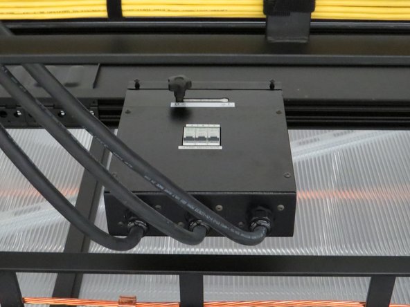
Ensure that the rack can be completely powered down (both AC and DC sources).
-
-
-
Remove the DC power covers and verify no voltage is present.
-
This is to verify that there is no potential risks of electrical shock.
-
-
-
Note: A fully powered down rack should NOT have any LED's still illuminated.
-
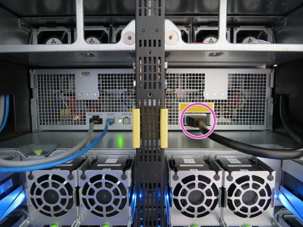
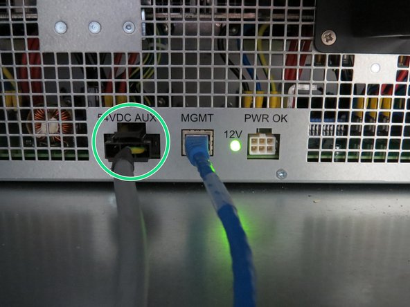
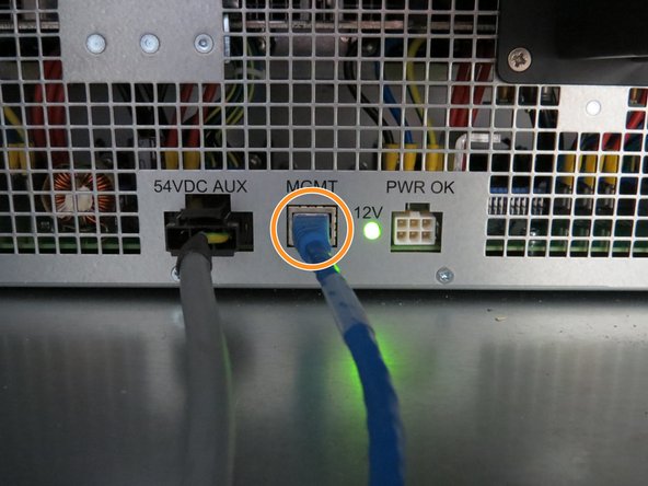
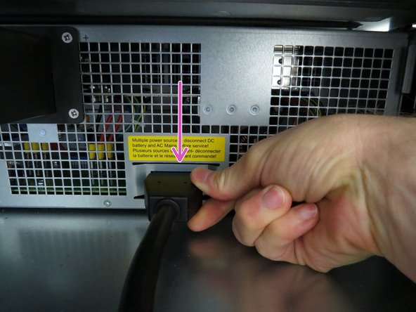
Disconnect the following rear cables to power down the power shelf:
-
AC Power Cable
-
54VDC AUX cable
-
RJ45 Ethernet cable
-
-
-
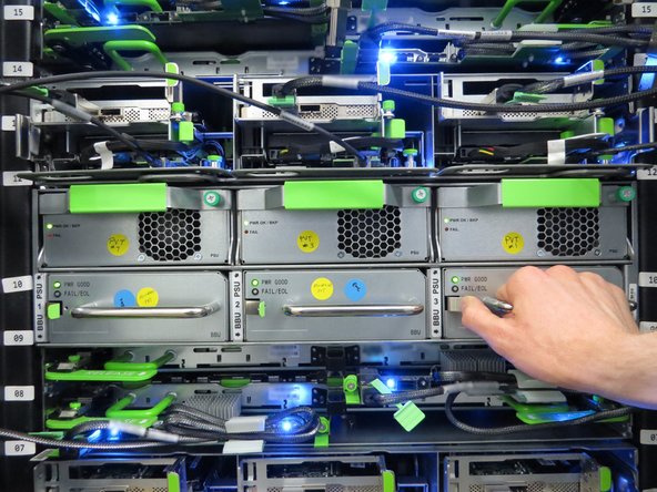
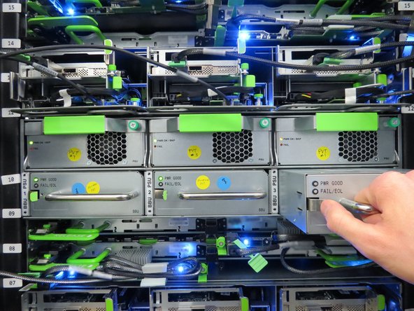
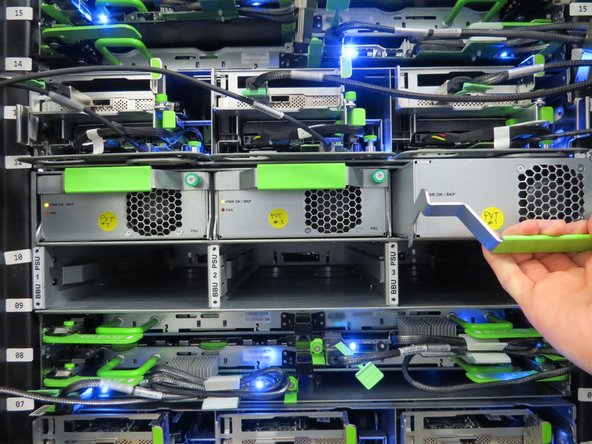
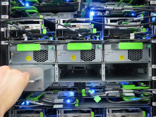
Remove all PSUsand BBUs.
-
These will be installed after the new power shelf is installed.
-
-
-
Prior to removing the output blade cover, ensure all PSUs and BBUs have been removed or unseated to eliminate potential risk of shock.
-
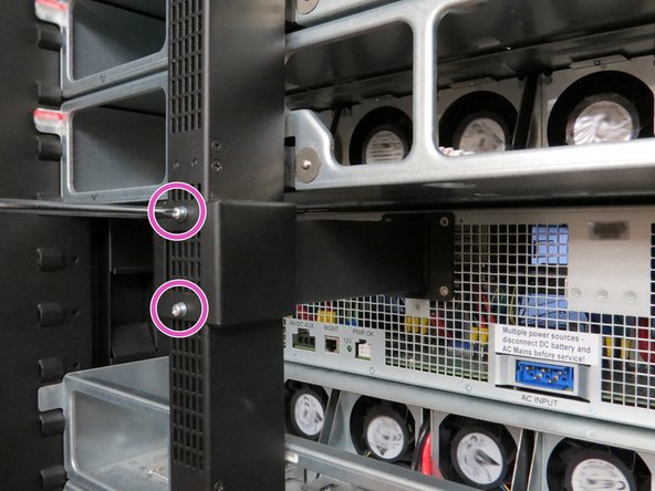
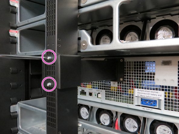
Locate the output blade cover at the rear of the rack and remove (2) Phillips head screws.
-
-
-
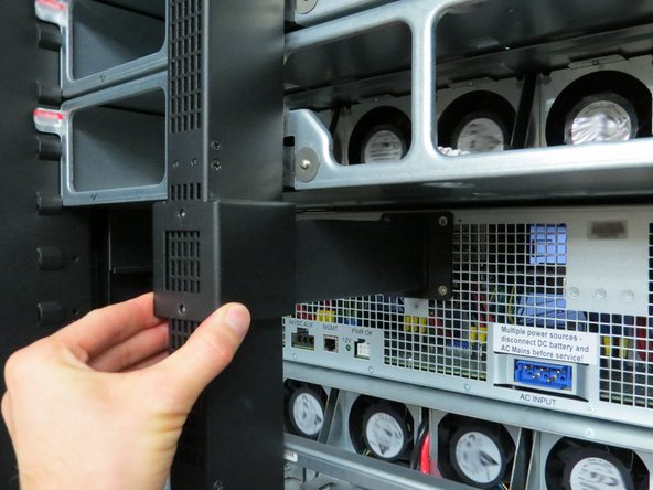
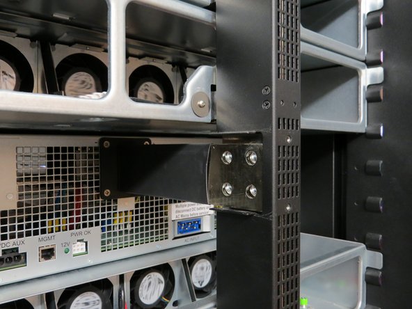
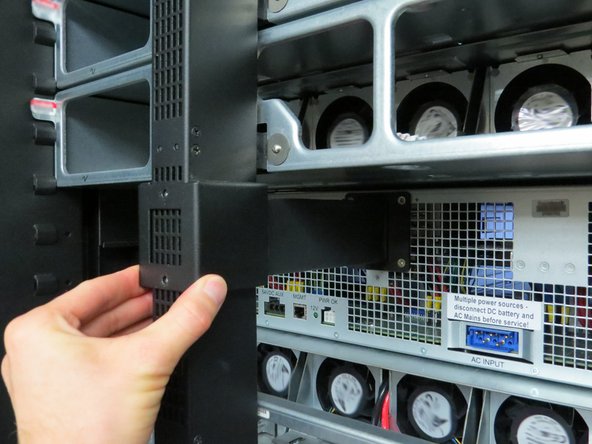
Remove the cover to expose the bus bar connection.
-
-
-
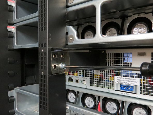
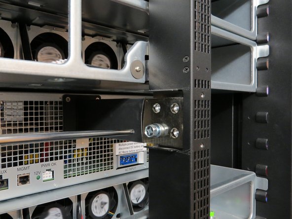
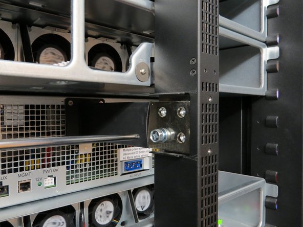
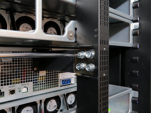
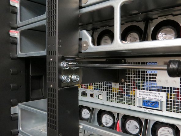
Remove (4) Phillips head screws from each output blade.
-
Some racks may have 5mm allen wrench bolts. A small wrench may be required for clearance.
-
-
-
Continue removing the remaining screws until the output blade is free from the bus bar.
-
-
-
Remove (2) screws located on each side of the power shelf chassis.
-
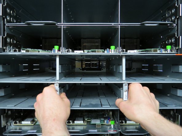
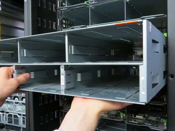
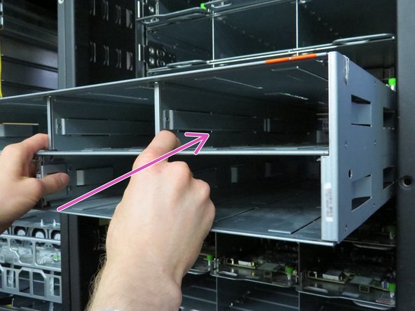
Slide the empty power shelf out from the rack (as shown).
-
-
-
Place your hand under the power shelf to counterbalance the weight.
-
Move the power shelf to a crash cart or work bench.
-
-
-
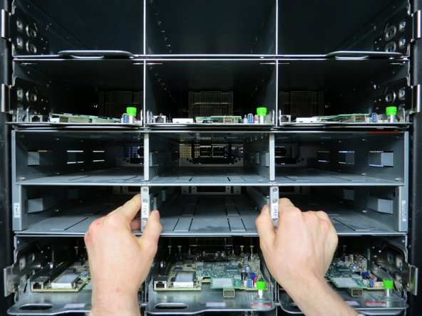
Carefully insert the new power shelf as shown.
-
-
-
Insert the power shelf until resistance is felt.
-
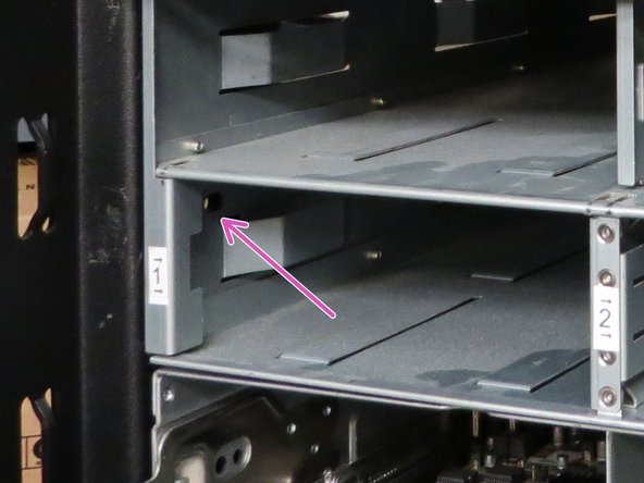
Secure the chassis by installing the (2) screws that were previously removed.
-
-
-
Make your way to the rear of the server rack to reconnect the output blade to the bus bar.
-
Insert (4) Phillips head screws into each output blade.
-
-
-
Install the second set of (4) Phillips head screws.
-
-
-
Install the metal cover to conceal the bus bar connection.
-
-
-
Install (2) Phillips head screws as shown.
-
-
-
Install all PSUs and BBUs back into the power shelf.
-
-
-
Refer to the PSU Replacement guide, if necessary.
-
Refer to the BBU Replacement guide, if necessary.
-
-
-
Note: A fully powered down rack should NOT have any LEDs still illuminated.
-
Connect the following rear cables:
-
AC Power input
-
54VDC AUX cable
-
RJ45 Ethernet cable
-
-
-
Verify with your facilities team that the rack is ready to be powered on.
-
-
-
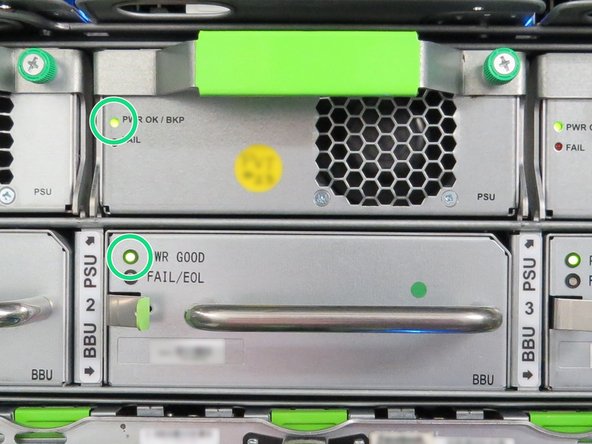
Ensure all PSU and BBU LEDs display solid green. This indicates no failures have occurred.
-







This work is licensed under a Creative Commons Attribution 4.0 International License.
This work is licensed under a Creative Commons Attribution 4.0 International License.
