
-
-
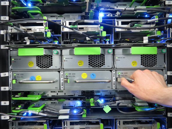
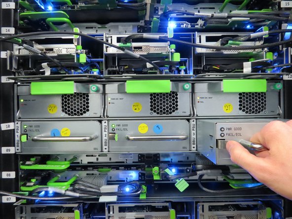
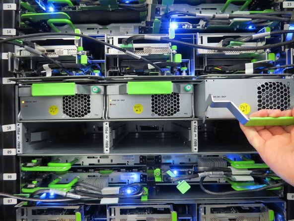
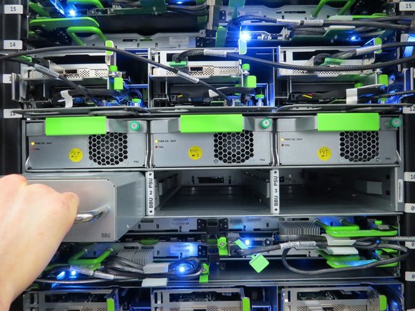
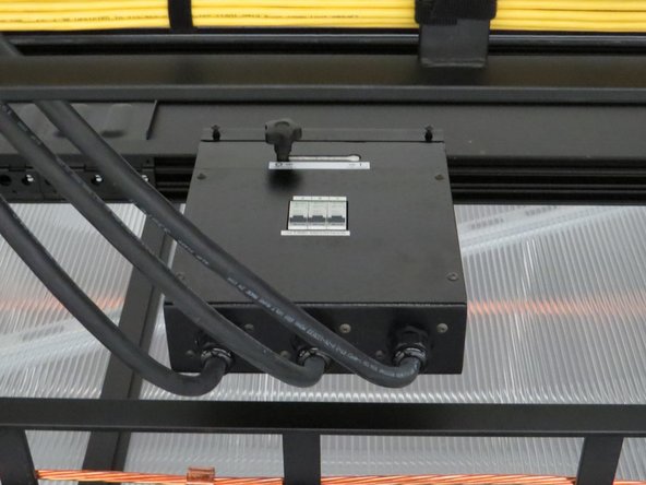
Ensure that the rack can be completely powered down (both AC and DC sources).
-
-
-
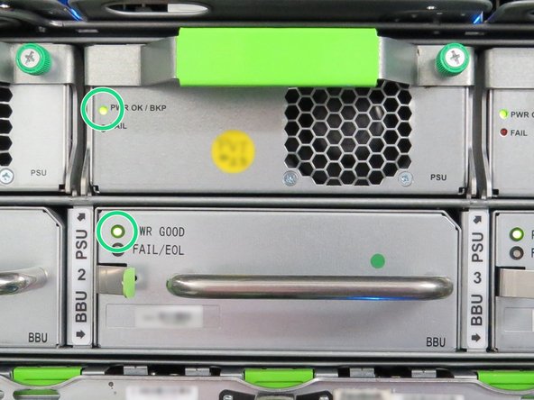
Note: A fully powered down rack should NOT have any LED's still illuminated.
-
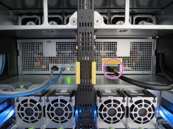
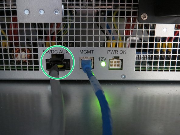
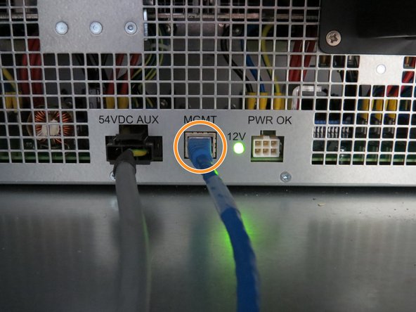
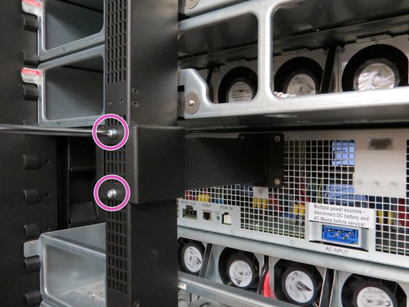
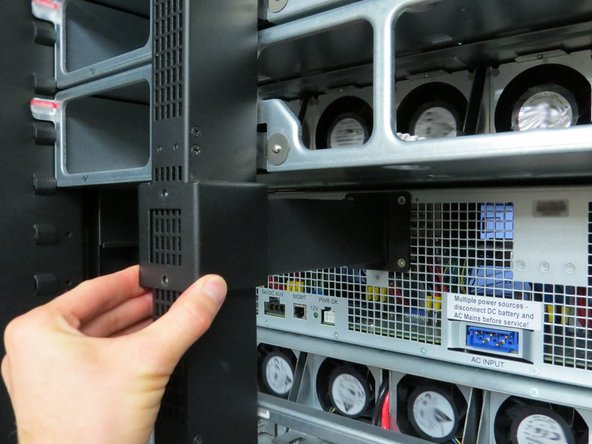
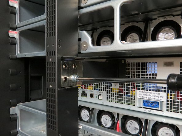
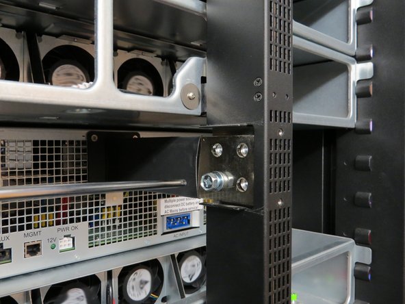
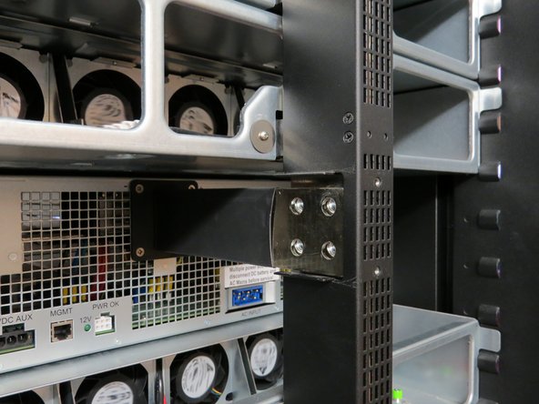
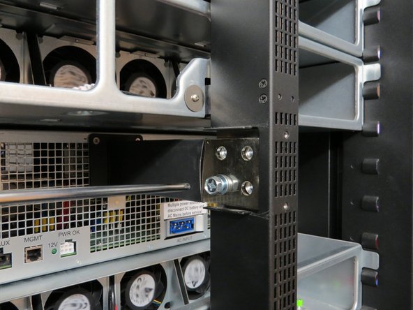
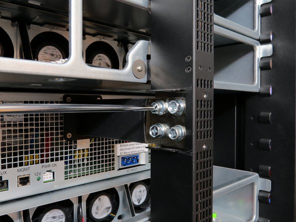
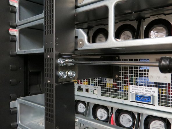
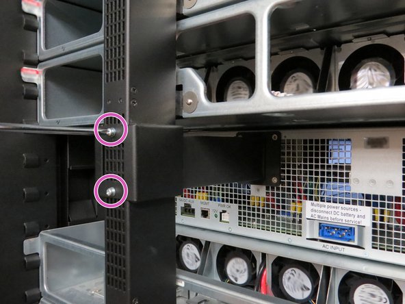
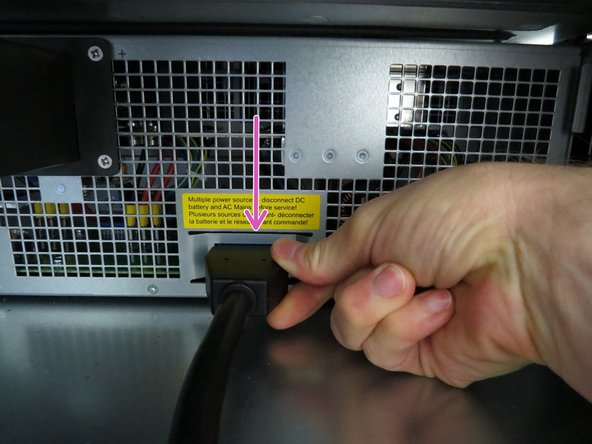
Disconnect the following rear cables to power down the power shelf:
-
AC Power Cable
-
54VDC AUX cable
-
RJ45 Ethernet cable
-
-
-
Verify with your facilities team that the rack is ready to be powered on.
-


Almost done!
This work is licensed under a Creative Commons Attribution 4.0 International License.
Conclusion
This work is licensed under a Creative Commons Attribution 4.0 International License.
